Actuation device

a technology of actuation device and winding wire, which is applied in the direction of coils, electrical devices, electromagnets, etc., can solve the problems of material weakening and winding wire tearout, and achieve the effect of improving the longevity of the actuation device and reliably preventing the damage of the winding wir

Active Publication Date: 2016-06-14
ETO MAGNETIC GMBH
View PDF6 Cites 0 Cited by
  • Summary
  • Abstract
  • Description
  • Claims
  • Application Information

AI Technical Summary

Benefits of technology

[0005]Starting from the previously mentioned prior art, the invention is based on the object of specifying an electromagnetic actuation device with at least one bent contact element, wherein damage of the winding wire fixed on the contact element is reliably avoided during the bending of the same. Preferably, it should not be necessary to relieve the winding wire, which is preferably constructed as varnished copper wire, in terms of process technology as early as in the winding process.
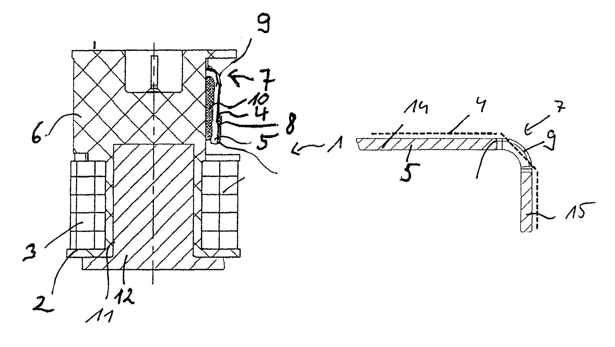
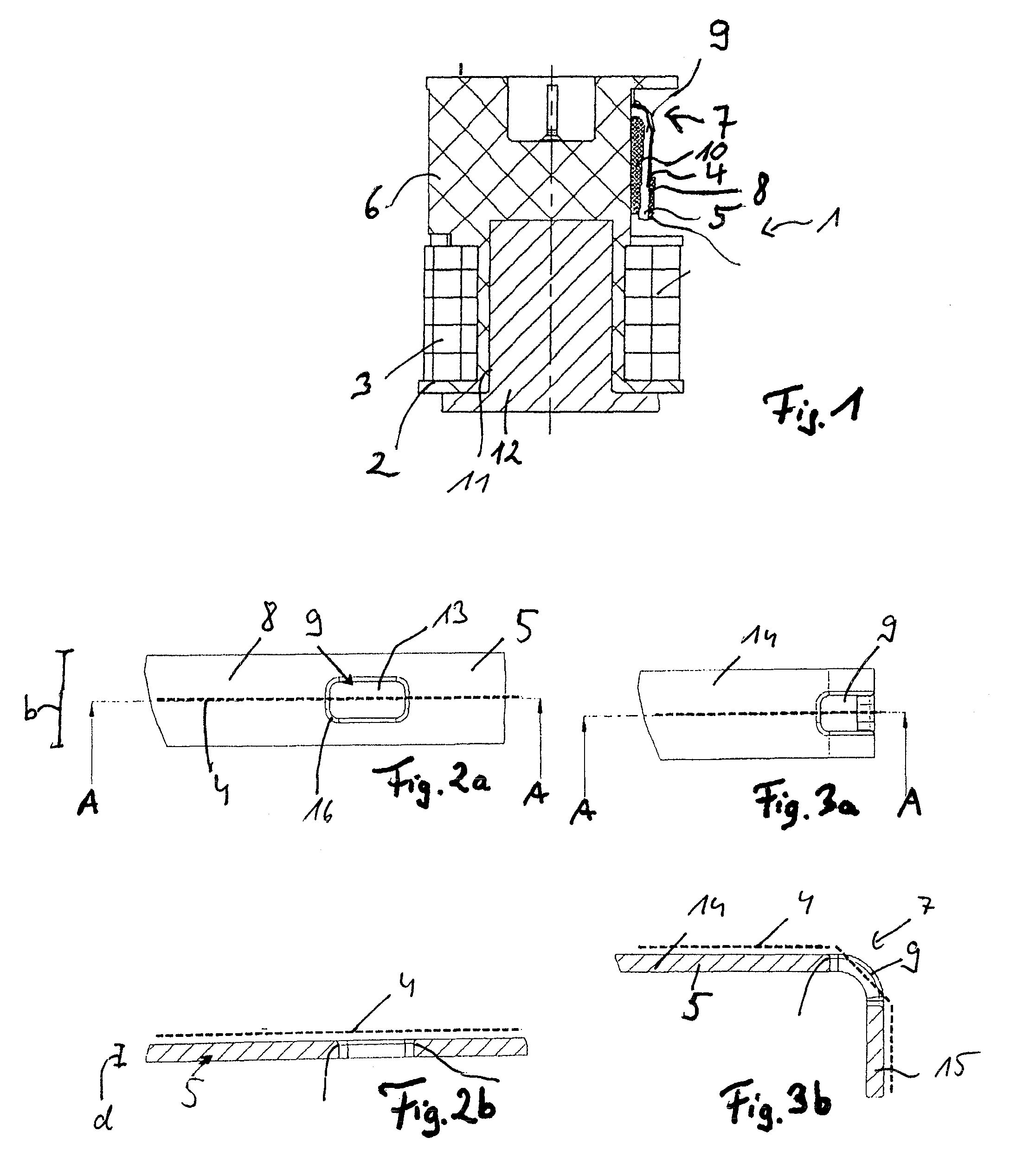
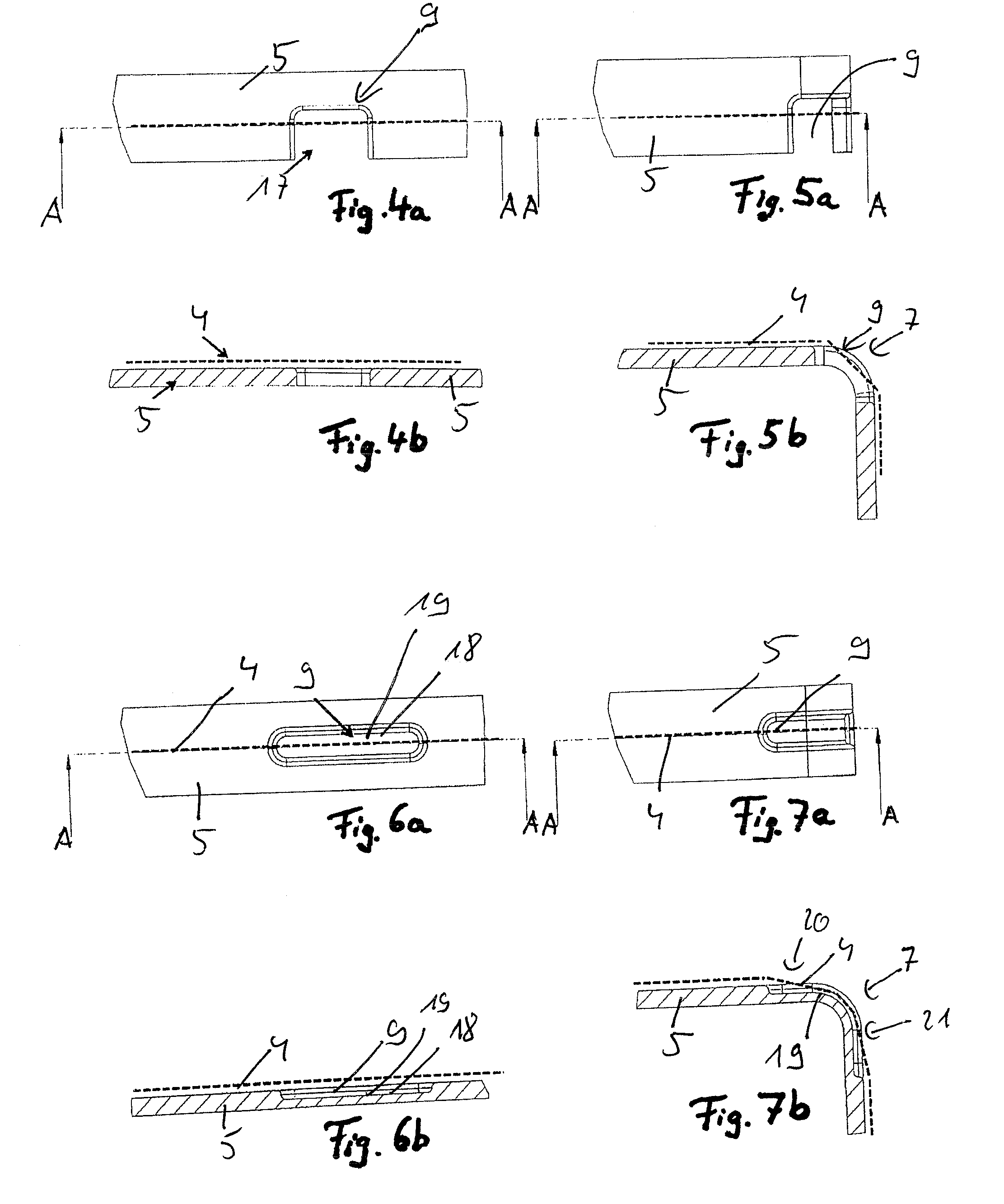
[0006]This object is achieved in the case of a generic electromagnetic actuation device in that the contact element has a depression geometry in the bending region, which shortens the bending path of the winding wire (compared to a conventional contact element) and through which the winding wire passes.
[0008]The invention avoids unacceptable tensile stress on the winding wire, which is in particular constructed as varnished copper wire, by means of the provision of a depression geometry in the contact element, through which the winding wire is passed and thus must only extend over a shorter path than if the winding wire were guided along a non-depressed external surface of the contact element, as in the prior art. Thus, on the basis of the invention, the route to be bridged by the winding wire in a region between the start and the end of the bending region is shortened compared to an embodiment of the contact element without such a depression, that is to say compared to contact elements known from the prior art, in which the winding wire is guided or arranged lying on the contact element at the outer radius of the bending region. Compared to the prior art, the winding wire preferably does not have a continuous arc shape due to the depression geometry in the bending region of the contact element. Preferably, the depression geometry is dimensioned such that the winding wire experiences no or at worst a slight tensile stress during the bending process, in which the contact element is preferably bent by approximately 90°, further preferably in such a manner that the end section thereof runs at least approximately parallel to the adjustment axis. Particularly preferably, a plastic deformation of the winding wire during the bending process of the contact element is completely prevented by means of the provision of a correspondingly configured depression geometry, which in turn leads to the prevention of strength reduction or even a tearing out of the winding wire. A depression geometry is understood to mean a geometry extending in the direction of the thickness extent of the contact element and thus both perpendicularly to the width extent and perpendicularly to the longitudinal extent of the contact element, due to which the winding wire assumes a smaller radius of curvature, i.e. a shorter distance must be bridged than a conceived outer shell contour of the contact element which spans the depression geometry or than the external surface laterally adjacent to the depression geometry.
[0015]It is particularly expedient if the depression geometry has a larger longitudinal extent than width extent. Preferably, the depression geometry should be dimensioned in just such a manner that the winding wire does not receive too much relief, in order to prevent damage, particularly cold hardening, due to internal combustion engine vibrations and tearing caused thereby.
[0019]For further improving the longevity of the actuation device, it is preferred if the depression geometry is provided with a radius in at least one transition region, preferably in both transition regions to the contact element surface which is not depressed in relation to the depression geometry, in order to reliably prevent damage of the winding wire.

Problems solved by technology

This can in turn lead to a material weakening and in the extreme case to a tearing out of the winding wire.

Method used


Image

  • Actuation device
  • Actuation device
  • Actuation device

Examples


Embodiment Construction

[0043]In the figures, the same elements and elements with the same function are characterised with the same reference numbers.

[0044]An electromagnetic actuation device 1 is shown in FIG. 1, which interacts in an actuating manner with an actuation partner, for example a camshaft hub shifting, which is not shown. The electromagnetic actuation device comprises a stator 2 with a coil winding 3, wherein an actuation element (armature) which is not illustrated is guided in an axially adjustable manner centrally in the interior of the actuator. To adjust the actuation element, current flows in the coil winding 3, more precisely the winding wire 4 thereof. To contact the winding wire 4, the same is electrically conductively connected at both ends to one tab-shaped contact element 5 in each case, which contact element is guided radially out of a support 6 constructed from plastic and bent by approximately 90° outside of the support 6 in a bending region 7. The winding wire runs on the contac...


PUM

PropertyMeasurementUnit
widthaaaaaaaaaa
widthaaaaaaaaaa
widthaaaaaaaaaa

Abstract

An electromagnetic actuation device with an actuation element, which can be adjusted relative to a stator on the basis of a magnetic actuation force which can be generated by the stator, wherein the stator has a coil winding, the winding wire of which is guided to a contact element bent at a bending region and is fixedly and electrically conductively connected to the same, wherein the contact element (5) has a depression geometry (9) in a bending region (7), which shortens a bending path of the winding wire (4) and through which the winding wire (4) passes.

Description

BACKGROUND OF THE INVENTION[0001]The invention relates to an electromagnetic actuation device with an in particular elongated actuation element which preferably has a permanent magnet means and can be adjusted relative to a stator on the basis of a magnetic actuation force which can be generated by the stator, wherein the stator has a coil winding, the winding wire of which is guided to a contact element bent at a bending region and is fixedly and electrically conductively connected to the same.[0002]Devices of this type have been known for a long time and are used for manifold purposes. The basic principle consists in a for the most part piston-like actuation element, which has an engagement region for the envisaged actuation task at the end, being guided in a generally magnetically conductive housing as armature between a stationary core region and a bearing element acting as yoke and being actuatable by means of an electromagnet (coil winding) provided in the core region for exam...

Claims


Application Information

Patent Timeline
Patent Type & Authority Patents(United States)
IPC IPC(8): H01H51/34H01F5/00H01F5/04H01F7/06
CPCH01F5/04H01F7/06H01F5/00
Inventor GOLZ, THOMAS
Owner ETO MAGNETIC GMBH
Why Eureka
Try Eureka