Electric linear motion actuator and electric disk brake system

a technology of actuator and actuator, which is applied in the direction of mechanical energy handling, mechanical equipment, mechanical equipment, etc., can solve the problems of actuators being large in size, difficult to smoothly and linearly move the carrier and the braking member, and the actuator cannot increase the power to the extent required in the electric disk brake system, etc., to prevent the inclination of the planetary roller, prevent the wear of the radially outer surface, and guide smooth

Active Publication Date: 2016-06-14
NTN CORP
View PDF23 Cites 1 Cited by
  • Summary
  • Abstract
  • Description
  • Claims
  • Application Information

AI Technical Summary

Benefits of technology

[0014]An object of the present invention is to allow smooth linear motion of the output member even when a lateral moment acts on the output member, to prevent wear of the radially outer surfaces of the planetary rollers and the radially inner surface of the outer ring member, and to prevent the shoulders of the helical rib from contacting the edges of the circumferential grooves or helical grooves when the helical rib is engaged in the circumferential grooves or helical grooves.

Problems solved by technology

But these mechanisms cannot increase power to an extent required in an electric disk brake system.
Such actuators tend to be large in size because they include an additional speed reducer.
But since the carrier, which is linearly moved, is relatively short in axial dimension, if this type of electric linear motion actuator is used e.g. in an electric brake system, a tangential force applied to the braking member (driven member) from the member to be braked partially acts on the carrier as a lateral moment, making it difficult to smoothly and linearly move the carrier and the braking member.
When the planetary rollers incline in radial directions or in the circumferential direction, the helical rib tends to be unevenly brought into contact with the circumferential grooves or the helical grooves, producing locally excessive loads on the contact portions between the helical rib and the circumferential grooves or helical grooves, which could partially break the helical rib or the circumferential grooves or helical grooves.
If the helical rib of the outer ring member and / or the circumferential grooves or helical grooves of the planetary rollers become worn, the contact pressure may become excessive between some turns of the helical rib and the circumferential grooves or helical grooves due to uneven contact therebetween, which could cause seizure and / or chipping at the contact portions.
The torque loss resulting from the contact resistance between the shoulders and edges reduces the efficiency of conversion to linear motion.
The contact between the shoulders and edges could also cause wear of, or damage to, the shoulders and / or edges.

Method used


Image

  • Electric linear motion actuator and electric disk brake system
  • Electric linear motion actuator and electric disk brake system
  • Electric linear motion actuator and electric disk brake system

Examples


Embodiment Construction

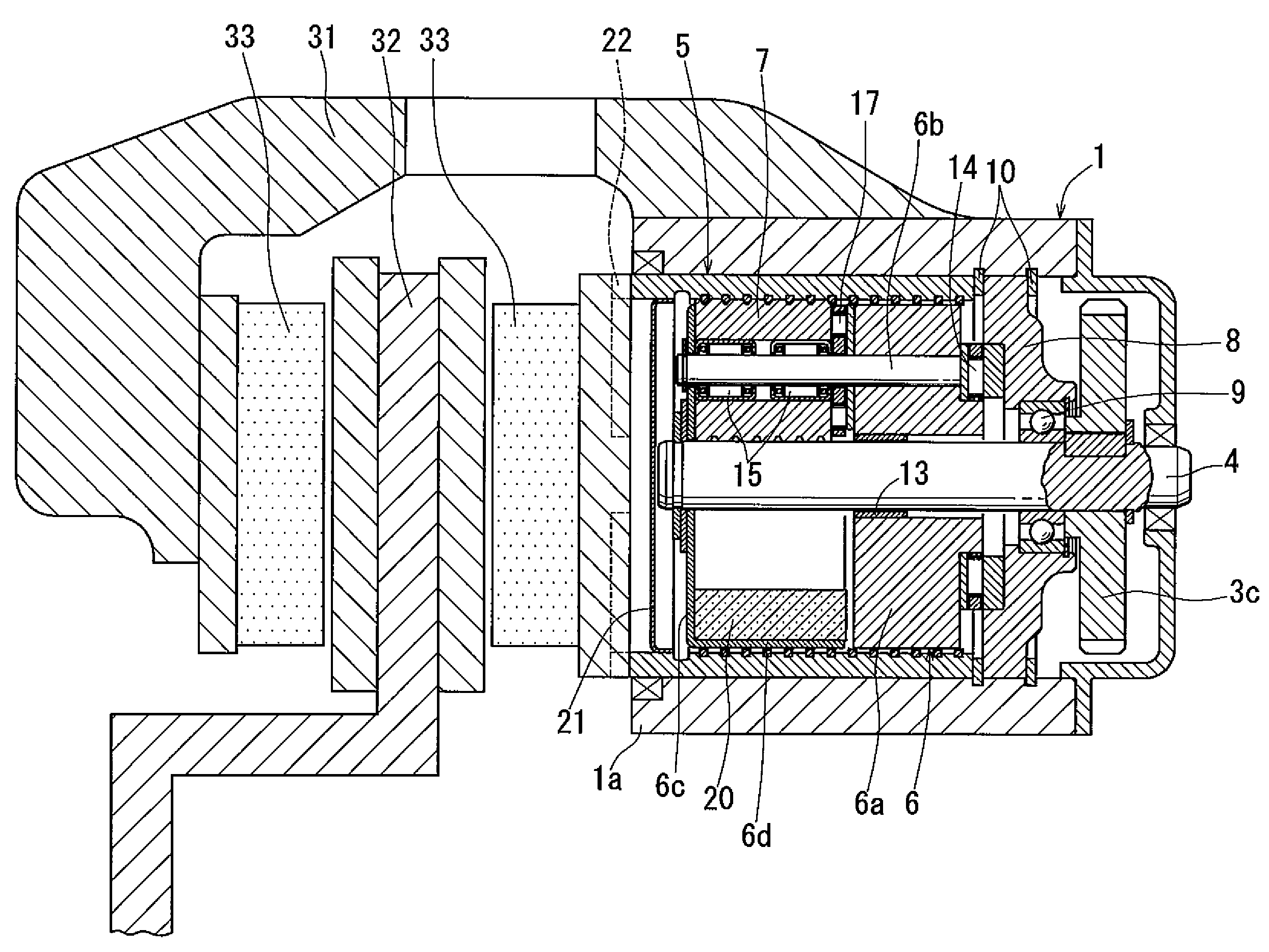
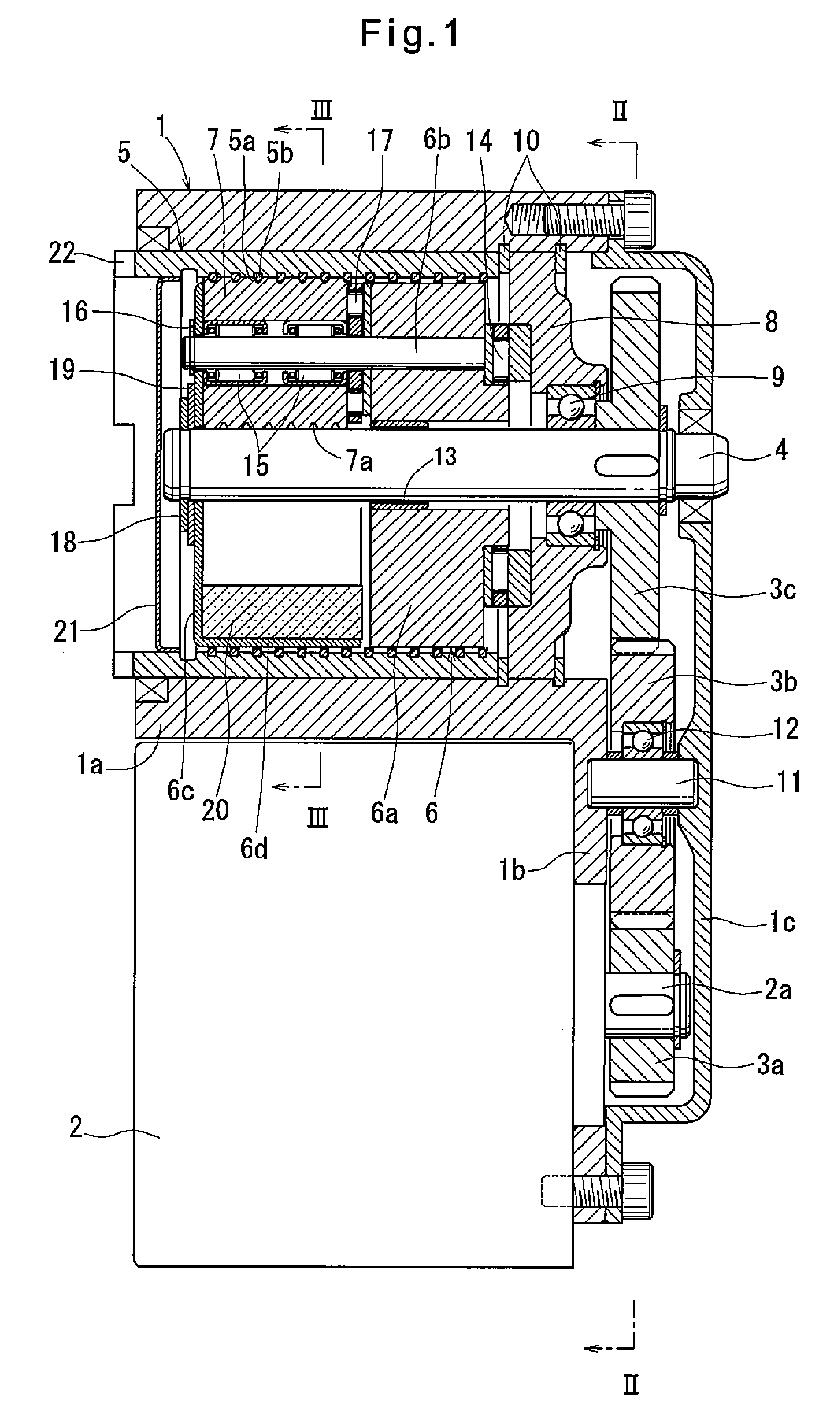
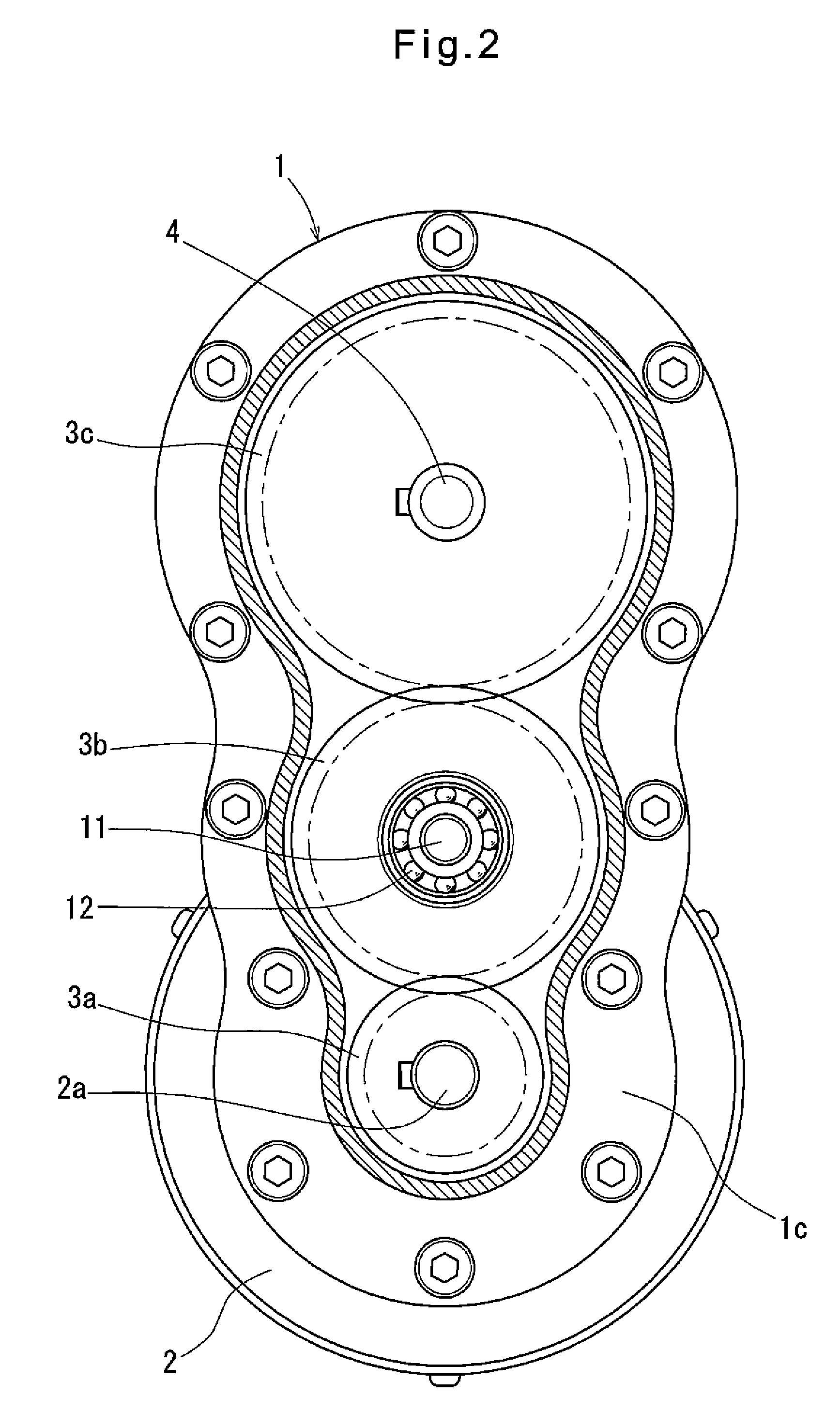
[0056]Embodiments of the present invention are now described with reference to the drawings. FIGS. 1 to 5 show an electric linear motion actuator embodying the present invention. As shown in FIGS. 1 to 3, the actuator includes a housing 1 having a cylindrical portion 1a, and a flange 1b protruding outwardly in one radial direction from one end of the cylindrical portion 1a. An electric motor 2 is mounted on the flange 1b to extend parallel to the cylindrical portion 1a.

[0057]The electric motor 2 has a rotor shaft 2a of which the rotation is transmitted to a rotary shaft 4 extending along the center axis of the cylindrical portion 1a through gears 3a, 3b and 3c. Four planetary rollers 7 are mounted between the rotary shaft 4 and an outer ring member 5 slidably fitted in the radially inner surface of the cylindrical portion 1a. The planetary rollers 7 are individually rotatably supported by a carrier 6. As shown in FIGS. 1 and 3, the outer surfaces of the rollers 7 are engaged agains...


PUM


Abstract

A linear motion actuator has an output member that can be smoothly moved linearly even when lateral moment acts on the output member. A carrier (6) supporting planetary rollers (7) is axially immovable, while an outer ring member (5), as the output member, is axially slidably fitted in the radially inner surface of a cylindrical portion (1a) of a housing (1), and is rotationally fixed to a driven member through keys (22). Hard plating layers are formed on the radially outer surface of a rotary shaft (4), the radially outer surfaces of the planetary rollers (7), including helical grooves (7a), and the surface of a helical rib member (5b) which is fixed to the radially inner surface of the outer ring member (5) forming a helical rib.

Description

TECHNICAL FIELD[0001]This invention relates to an electric linear motion actuator for converting the rotary motion of an electric motor to a linear motion and linearly driving a member to be driven, and an electric disk brake system using such an electric linear motion actuator.BACKGROUND ART[0002]Typically, a conventional electric linear motion actuator of this type includes a ball screw mechanism or a ball-ramp mechanism as a motion converter for converting rotary motion to linear motion.[0003]Ball screw mechanisms and ball-ramp mechanisms used in such electric linear motion actuators convert rotary motion to linear motion utilizing a thread having a lead angle, and inclined cam surfaces, respectively, such that they can increase power to a certain extent. But these mechanisms cannot increase power to an extent required in an electric disk brake system.[0004]Electric linear motion actuators including such a motion converter further include a speed reducer such as a planetary gear ...

Claims


Application Information

Patent Timeline
Patent Type & Authority Patents(United States)
IPC IPC(8): F16D65/18H02K7/06F16H25/22F16D121/24F16D125/40F16D125/48
CPCF16D65/18F16H25/2252H02K7/06F16D2121/24F16D2125/40F16D2125/48Y10T74/18656F16D2125/50F16H19/025
Inventor YAMASAKI, TATSUYAEGUCHI, MASAAKI
Owner NTN CORP
Why Eureka
Try Eureka