
Heat-shrink tubing process apparatus and method of making heat-shrink tubing

a technology process apparatus, which is applied in the field of heat shrinking tubing process apparatus and a method of making heat shrinking polymeric tubes, can solve the problems of tubing shrinkage, and achieve the effects of quick cooling of tubing, and locking in residual stress

Active Publication Date: 2016-06-21
FLUORON
View PDF14 Cites 3 Cited by
  • Summary
  • Abstract
  • Description
  • Claims
  • Application Information

AI Technical Summary

Benefits of technology

The patent describes a process apparatus for making heat-shrink tubing. The apparatus includes a first chamber for heating and expanding the tubing, followed by a pinch-roll apparatus for cooling the tubing. The cooling can be done using a second chamber with a lower temperature fluid. The apparatus can be coupled or separated, and a diaphragm can be used to reduce fluid leakage between the chambers. The expansion element, which is used to expand the tubing, has a tapered leading and trailing portion, and may be made of metal or plastic. The method involves inserting the expansion element into the tubing, configuring the tubing through the heated chamber and the pinch-roll apparatus, starting the pinch-roll apparatus to pull the tubing through the process apparatus, and moving the pinch-roll apparatus to maintain the expansion element in a desired location. The technical effects of this patent include improved control over the heat-shrink tubing process, improved cooling of the tubing, and reduced fluid leakage between chambers.

Problems solved by technology

Residual stresses are locked into the tubing at the expanded diameter and subsequent heating causes the tubing to shrink.

Method used


Image

  • Heat-shrink tubing process apparatus and method of making heat-shrink tubing
  • Heat-shrink tubing process apparatus and method of making heat-shrink tubing
  • Heat-shrink tubing process apparatus and method of making heat-shrink tubing

Examples


Embodiment Construction

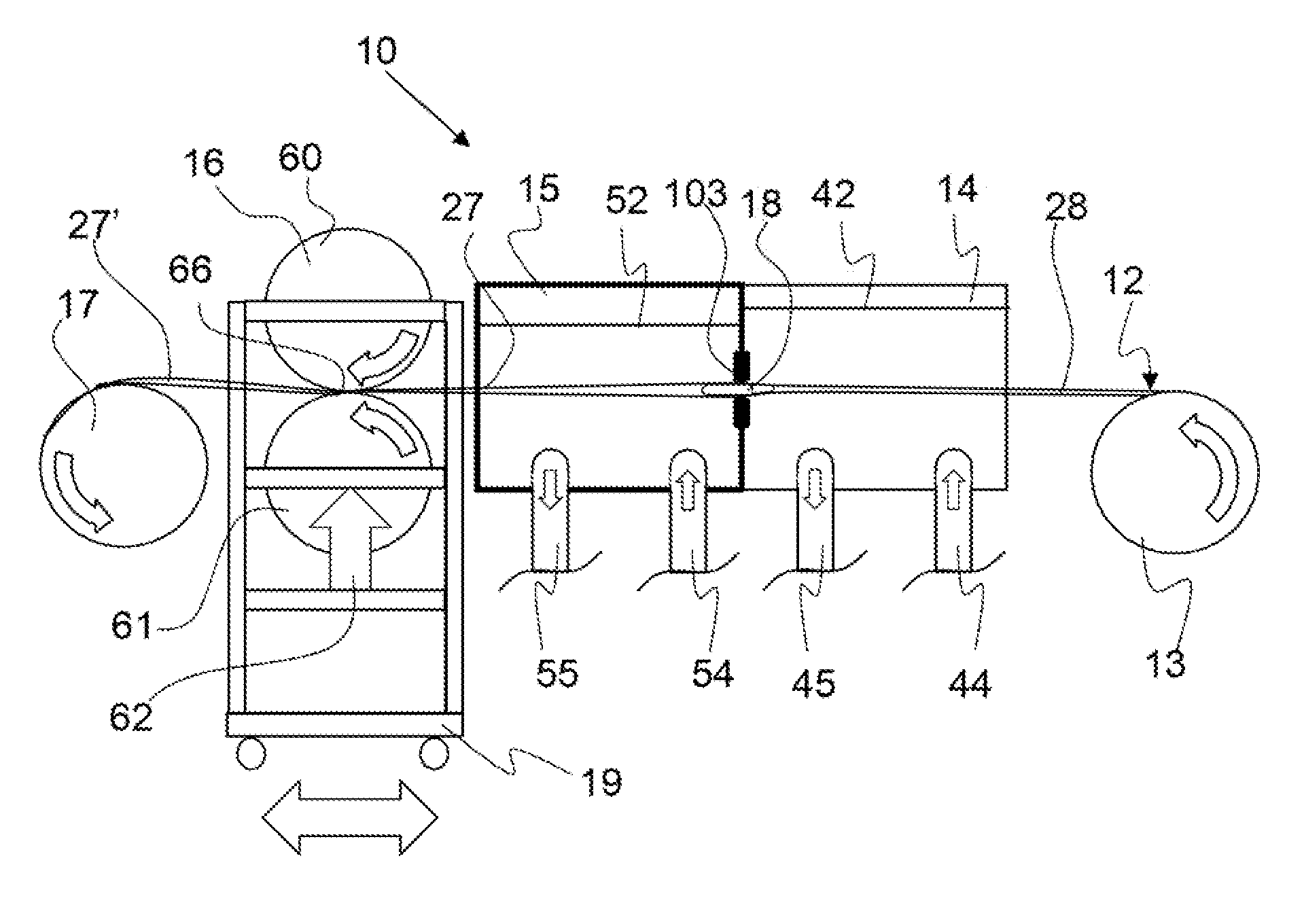
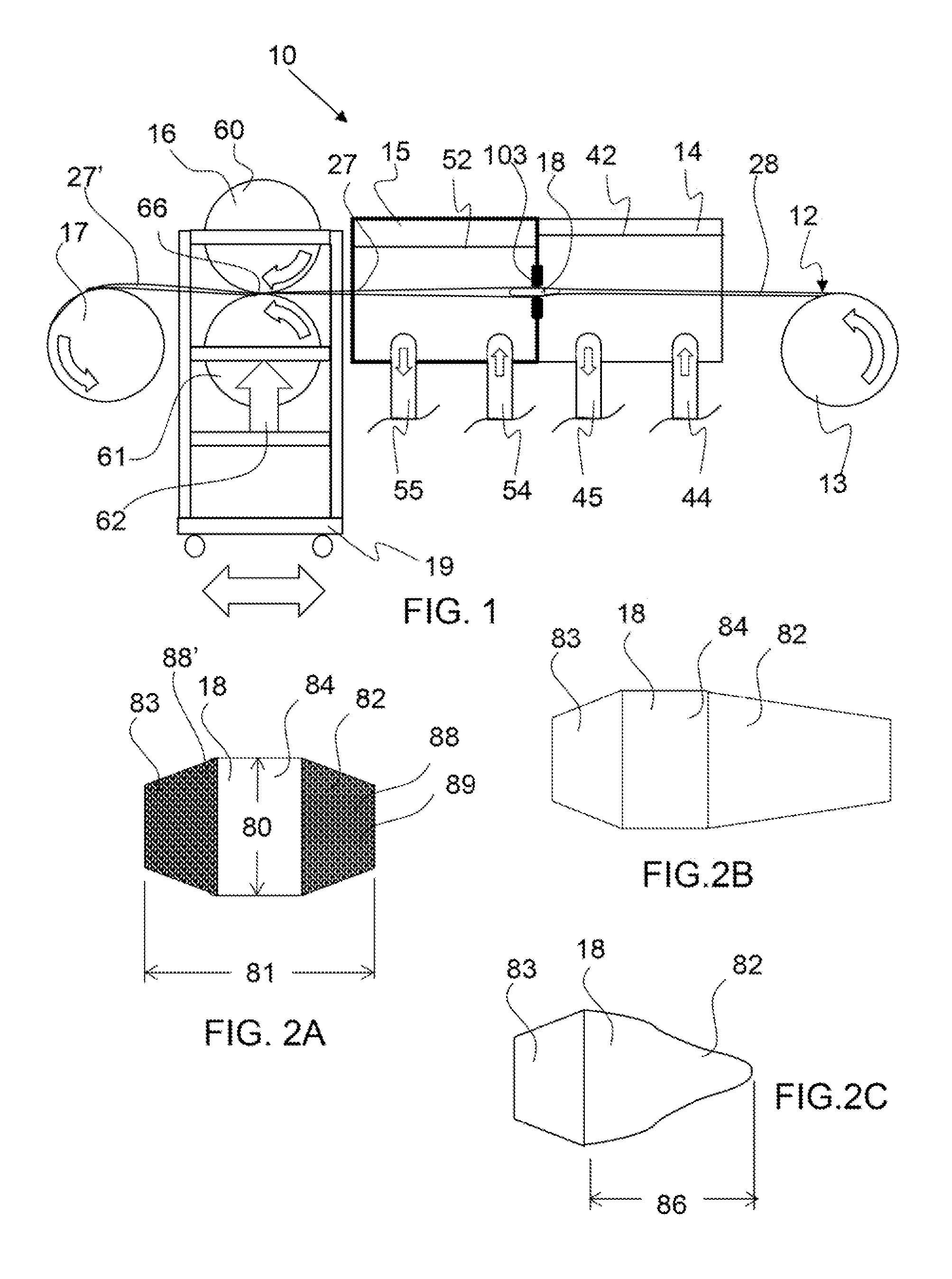
[0020]FIG. 1 shows a side view of an exemplary embodiment of a heat-shrink tubing process apparatus as described herein.

[0021]FIG. 2A shows a side view of an exemplary expansion element as described herein.

[0022]FIG. 2B shows a side view of an exemplary expansion element as described herein.

[0023]FIG. 2C shows a side view of an exemplary expansion element as described herein.

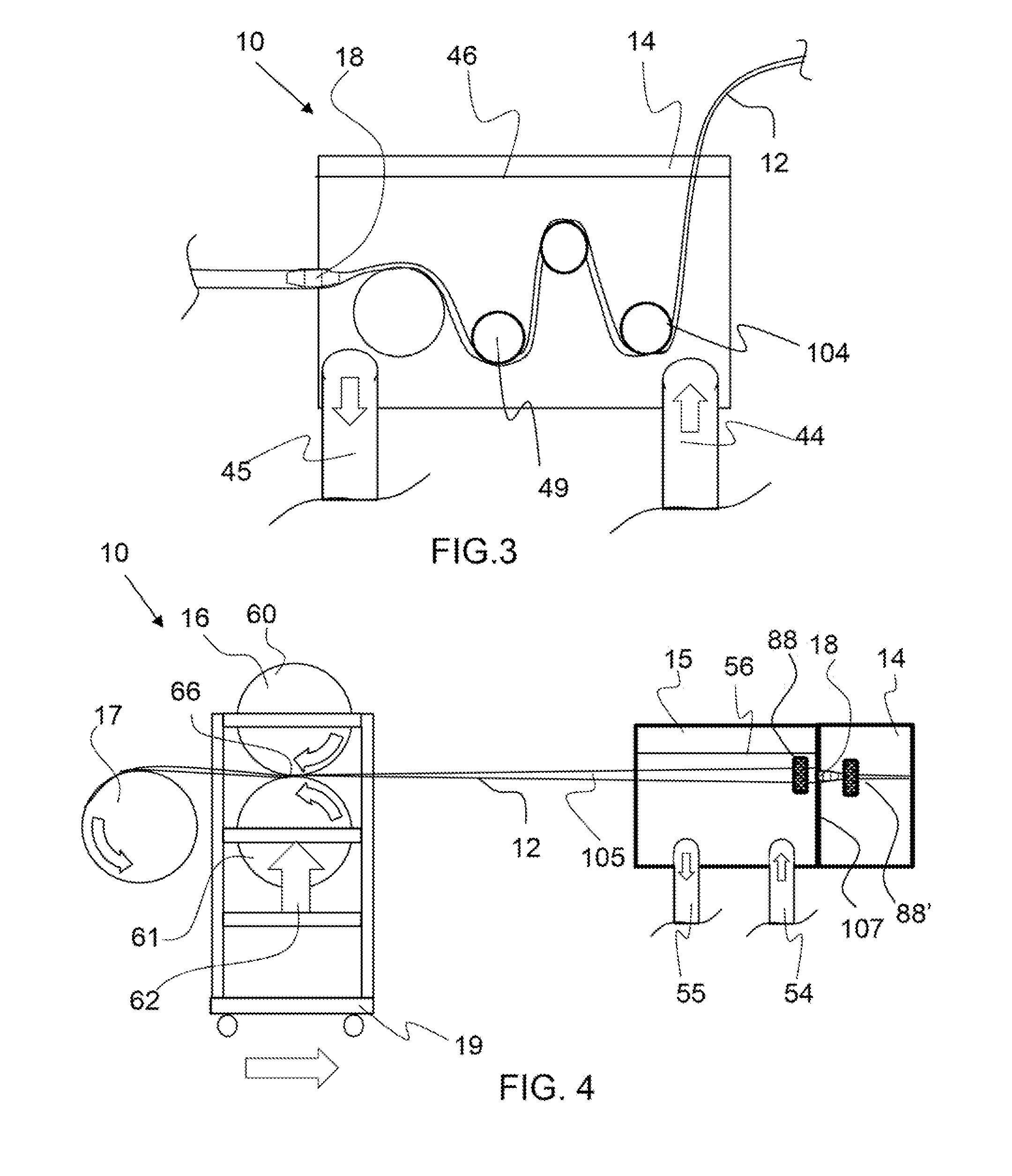
[0024]FIG. 3 shows a side view of an exemplary chamber having an accumulator as described herein.

[0025]FIG. 4 shows a side view of a portion of an exemplary heat-shrink tubing process apparatus as described herein having a pinch-roll apparatus on a conveyor.

[0026]FIG. 5 shows a side view of a portion of an exemplary heat-shrink tubing process apparatus as described herein having a temperature sensor and an expansion element location sensor and a conveyor controller.

[0027]FIG. 6 shows a side view of an exemplary seal as described herein.

[0028]FIG. 7A shows a side view of a tubing extruder having an expansion elem...


PUM

PropertyMeasurementUnit
Fractionaaaaaaaaaa
Temperatureaaaaaaaaaa
Pressureaaaaaaaaaa

Abstract

A continuous heat-shrink tubing process is described having an expansion element disposed with the tubing and a position maintenance feature to keep the expansion element in a desired location. The expansion element may be maintained in a position by pressurized fluid trapped within the tubing between the expansion element and pinch rollers. The pinch roller may be moved to reduce the volume within the section of tubing between the pinch roller nip and the expansion element, and thereby increase the pressure of the trapped fluid. In another embodiment, the expansion element may be held in place by an extruder connector. In yet another embodiment, the expansion element incorporates a magnetic component, or has at least one magnet, or magnetic metals and one or more magnets are configured to maintain an expansion element position through attractive or repulsive magnetic forces.

Description

CROSS REFERENCE TO RELATED APPLICATIONS[0001]This application claims the benefit of U.S. provisional patent application No. 61 / 648,613 filed on May 18, 2012 and entitled Heat-Shrink Tubing Process Apparatus and Method of Making Heat-Shrink Tubing, which is incorporated by reference herein in its entirety.BACKGROUND OF THE INVENTION[0002]1. Field of the Invention[0003]The present invention relates to a heat-shrink tubing process apparatus and a method of making a thermally shrinkable polymeric tube, or heat-shrink tube, and in particular a fluoropolymer heat-shrink tube.[0004]2. Background[0005]Heat-shrink tubes are used in a variety of applications including, but not limited to, mandrel and roll covers that are used in various processes including electronic devices, such as copiers, electrical wire and cable covers, fluorescent light bulbs, joints and terminal ends and the fabrication of carbon fiber reinforced plastic shapes. Discrete lengths of heat-shrink tubing can be made by he...

Claims


Application Information

Patent Timeline
IPC IPC(8): B29C57/04B29D23/00
CPCB29D23/00B29C55/24B29D23/001
Inventor CHAPMAN, FRANK MYRONGEARY, CHRISTOPHER LEE
Owner FLUORON
Learn More