Ship having an opening for removing a power supply system

a power supply system and power supply technology, applied in the field of ships, can solve the problems of only being able to carry out installation and removal operations, and being unable to carry out, and achieve the effects of reducing complication and expenditure, avoiding endangering the operation of the ship, and reducing the cost of operation

Active Publication Date: 2016-06-28
WOBBEN PROPERTIES GMBH
View PDF37 Cites 3 Cited by
  • Summary
  • Abstract
  • Description
  • Claims
  • Application Information

AI Technical Summary

Benefits of technology

[0012]Preferably the common opening or common openings can be closed by means of a cover plate and extend through the ceiling above the diesel-electric systems. Further preferably a plurality of diesel-electric systems are respectively arranged in a common room, for example the engine room, with which the common opening is associated. The common room is preferably disposed beneath the hold, wherein the floor of the hold corresponds to the ceiling of the room containing the diesel-electric systems. Preferably a plurality of groups of diesel-electric systems are distributed in rooms over the ship, to achieve a more uniform distribution of mass. Preferably the rooms are arranged in the forecastle to provide a counter-weight to a drive for the ship's screw, which is arranged astern. Another particular advantage of the present invention also lies in the use of a plurality of diesel-electric systems in the energy supply system. If it is assumed that a given amount of energy is required on board a ship, it has hitherto been assumed in the case of known ships that it is most economical to design as few diesel-electric systems as possible, of the highest power output as possible, with large-size engines, to meet the anticipated situation in respect of power requirement, and to fit such large systems in the ship. The maintainability of a ship in accordance with the invention however is particularly advantageously influenced by virtue of the fact that, instead of as few large assemblies as possible, there is provided a plurality of smaller diesel-electric systems which can be respectively removed through the opening associated therewith, at a much lower level of complication and expenditure, for external maintenance operations. That is not possible in the case of a ship with only one or possibly a few large-scale systems.
[0013]The diesel-electric systems are movable within the ship between an operating position and a mounting / removal position beneath the common opening. The mobility of the diesel-electric systems between an operating position and a mounting / removal position means on the one hand that the utilization of space is improved within the room in which the diesel-electric systems are respectively arranged, for more easily passing through the room while the ship is moving or outside of an operation for replacing one or more diesel-electric systems. On the other hand, the time required for changing one or more diesel-electric systems can be still further reduced insofar as the diesel-electric system is already moved out of an operating position into the mounting / removal position before the beginning of the actual replacement operation, through the common opening. In that respect it is particularly advantageous that a plurality of diesel-electric systems is provided on board the ship. The number of diesel-electric systems is preferably so selected that not all diesel-electric systems of the ship are constantly in operation so that shutting down a diesel-electric system and moving it out of the operating position into the mounting / removal position can be compensated by the other diesel-electric systems. Moving the diesel-electric system from the operating position into the mounting / removal position makes it possible to prepare for the rapid replacement through the common opening, that is to say to already prepare for that operation before reaching a port in which the replacement operation is to be effected. Preferably there are three or more diesel-electric systems, particularly preferably six or more diesel-electric systems.
[0014]In a preferred embodiment the diesel-electric systems are displaceable by means of displacement means, preferably rails. The provision of displacement means make it possible to ensure that the diesel-electric systems are not moved in a free movement between the operating position and the mounting / removal position, but that such movement takes place along a defined and preferably guided path. That facilitates on the one hand positioning of the diesel-electric systems in the operating or mounting / removal position, and in addition reduces the risk of damage and / or injury to surrounding components or any operators during the movement of the diesel-electric systems.
[0015]As an alternative to a rail configuration, rollers or other sliding portions can be provided as the displacement means. The displacement means can preferably also include machine support of the movement, from one position into the other, for example hydraulic drives or pneumatic drives or block-and-tackle arrangements.
[0016]In a further preferred embodiment the ship has removable floor panels arranged above the displacement means. The floor panels are adapted to make it possible to go into the room in which the generators are arranged. At the same time the floor panels prevent operators being able to stumble over or damage the displacement means. The floor panels can be of such a configuration that displacement or movement of the diesel-electric systems by means of the displacement means is first made possible when the floor panels have been removed, thereby further increasing the aspect of passive safety.
[0017]The diesel-electric systems can preferably be arrested in the operating position. Arresting is preferably effected by means of screwing or latching. Such arresting means are particularly preferably provided in addition to the floor panels for arresting the diesel-electric systems, also in order to limit or prevent possible damage to the floor panels by unintentionally moving the diesel-electric systems relative to the floor panels.

Problems solved by technology

Installation and removal operations are only limitedly possible on the ship which, in the interior, affords only extremely limited space for arranging functional elements, in order to make the best possible use of the load-carrying volume.
That is not possible in the case of a ship with only one or possibly a few large-scale systems.

Method used


Image

  • Ship having an opening for removing a power supply system
  • Ship having an opening for removing a power supply system
  • Ship having an opening for removing a power supply system

Examples


Embodiment Construction

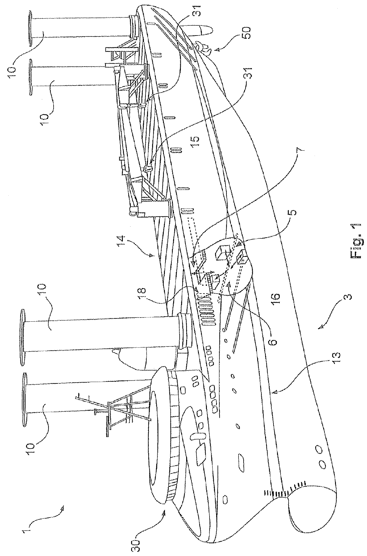
[0035]FIG. 1 shows a diagrammatic view of a ship 1 according to a first embodiment. In this case the ship 1 has a hull comprising an underwater region 16 and an above-water region 15. The ship 1 can further have for example four Magnus rotors or Flettner rotors 10 which can be arranged at the four corners of the hull. The ship 1 has a bridge 30 in the forecastle. The ship 1 has a propeller 50 underwater. For improved maneuverability the ship 1 can also have transverse thruster rudders, wherein preferably one is provided at the stern and one to two transverse thruster rudders are provided at the bow. Preferably those transverse thruster rudders are driven electrically. The bridge 30 and all superstructures above the weather deck 14 are of an aerodynamic configuration to reduce wind resistance. That is achieved in particular by sharp edges and sharp-edged structures being substantially avoided. As few superstructures as possible are provided to reduce wind resistances.

[0036]The ship 1...


PUM


Abstract

The invention relates to a ship, in particular a cargo ship, having a power supply system. The invention relates in particular to a ship having a plurality of diesel electric systems for providing electrical power that are disposed within the ship, wherein a plurality of diesel electric systems are each associated with a common opening for removing the diesel electric systems. The invention further relates to a power supply system for a ship and to a method for controlling the power supply system of a ship.

Description

BACKGROUND[0001]1. Technical Field[0002]The present invention concerns a ship, in particular a cargo ship, having an energy supply system. The invention further concerns an energy supply system for a ship, in particular a cargo ship. The invention further concerns a method of controlling an energy supply system of a ship.[0003]2. Description of the Related Art[0004]Ships of the aforementioned kind usually take electrical energy from an on-board energy supply system. In known ships the energy supply system has one or more diesel-electric systems which convert a mechanically produced power into electrical energy. The expression diesel-electric system is used to denote a system which is adapted to generate electrical energy and which has a (diesel) internal combustion engine for producing mechanical power, coupled to a generator for generating electrical energy.[0005]On ships of the kind set forth in the opening part of this specification the on-board network, communication devices, au...

Claims


Application Information

Patent Timeline
Patent Type & Authority Patents(United States)
IPC IPC(8): B63B3/54B63H21/30B63J3/02B63H9/02B63H21/17B63H21/21G06Q10/00
CPCB63B3/54B63H9/02B63H21/17B63H21/21B63H21/30B63J3/02G06Q10/20
Inventor ROHDEN, ROLF
Owner WOBBEN PROPERTIES GMBH
Why Eureka
Try Eureka