Delivery and extraction devices

a technology of extraction device and extraction chamber, which is applied in the field of extraction device and delivery, can solve the problems of additional bulk of secondary device, difficulty, and other problems, and achieve the effect of reducing the number of secondary devices, and reducing the number of patients

Inactive Publication Date: 2016-07-05
HICKINGBOTHAM DYSON +1
View PDF8 Cites 24 Cited by
  • Summary
  • Abstract
  • Description
  • Claims
  • Application Information

AI Technical Summary

Benefits of technology

[0019]In one embodiment, the mandrel guide of the device comprises a proximal length of guide and a nozzle coupled to the distal end of the proximal length of guide, wherein the nozzle is longitudinally fixed relative to the proximal length of guide and the delivery controller is operably linked to the delivery unit at a location proximal to the nozzle, optionally wherein the delivery controller is operably linked to the delivery unit inside the delivery unit support. Optionally, such a configuration allows for full insertion of the nozzle (e.g. pasta low-profile nozzle coupler). Optionally, the device comprises a nozzle which is non-cylindrical (e.g. shaped for delivering sheets and / or nanoplates) and / or curved (e.g. longitudinally arched), for example, when in position for delivery. Optionally, the nozzle is non-cylindrical (e.g. flattened or oblate) through the entire length (or a substantial portion) of the nozzle is alternatively cylindrical at the proximal end but non-cylindrical at the distal tip (e.g. oblately flared).

Problems solved by technology

Difficulty can arise when the substance intended for extraction or delivery is fragile and / or when the target site is blocked or partially blocked by a delicate environment.
Trauma to the surrounding environment or the substance itself can occur during the procedure in the event of off-target placement or unintentional movement of the device or extended duration of device use within the subject.
Further tissue insult can ensue from the additional bulk of secondary devices such as cameras or fluid jets sometimes used to aid the procedure.
Thus far, plunger-barrel type devices have fallen short on a number of levels including their precision of device mobility and placement, ability to perform multiple functions, and simplicity of use in applications where the substance itself or the environment surrounding the target is delicate, for example, implantation / extraction procedures for nervous, cardiac, vascular, bone, and joint tissue.
Unfortunately, this type of surgery is rendered extremely difficult by both a delicate surrounding environment and a fragile target substance.
These abnormalities in the subretinal space under the retina can damage the retina in the back of the eye and can lead to blindness.
The photoreceptors will then degenerate, resulting in vision loss or blindness, while the other layers of the retina may remain functional.
This results in impairment of central and / or peripheral vision.
Surgical correction of diseases in the subretinal space between the retina and the RPE is rendered extremely difficult by the environment in which the surgery must take place.
Moreover, the surgical procedure disclosed herein to implant retinal tissue into the subretinal space of the eye is complicated by the fact that fetal retinal tissue is in the nature of a transparent gelatinous mass with two non-interdigitated layers, the photoreceptors and RPE, and therefore extremely fragile.
However, none of U.S. Pat. No. 5,941,250; U.S. Pat. No. 6,159,218; and U.S. Pat. No. 6,156,042 teach a device with sensitive, error-reducing delivery control, a device having a nozzle that enables precise control of placement, or a device having a multifunctional mandrel.
U.S. Pat. No. 7,468,065 to Weber et al. describes a device for delivery of ocular implants, but like other devices discussed above, this device fails to meet the needs of applications involving fragile substances to be delivered or extracted, or where the target site is blocked by a delicate environment.

Method used


Image

  • Delivery and extraction devices
  • Delivery and extraction devices
  • Delivery and extraction devices

Examples


example 1

Device with Delivery Controller Linked Internally

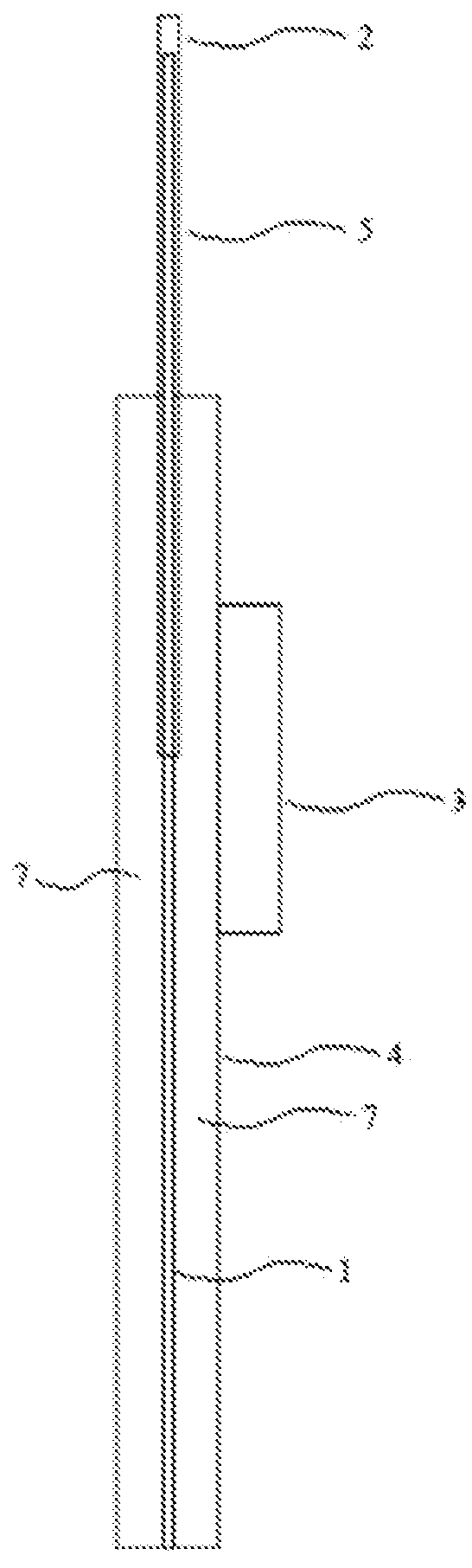
[0209]One embodiment of the present invention provides a device for delivering a substance, as depicted in FIG. 1. The device comprises a delivery unit 5 comprising a mandrel guide (e.g. 2) and a mandrel 1 disposed internally of the mandrel guide (e.g. 2). The delivery unit is supported by a delivery unit support 4. A delivery controller 3 is operably linked (operable linkage not shown) to the delivery unit 5 in the lumen 7 of the delivery unit support 4 to control longitudinal movement of the mandrel 1 relative to the mandrel guide (e.g. 2).

[0210]Surprisingly, such a configuration provides for easier maneuverability in the presence of other devices such as scopes and less obstruction of vision, for example, thereby reducing tissue trauma during a procedure. Such a configuration reduces bulk in comparison to prior art devices in which the delivery controller is linked, for example, directly to the nozzle externally of the mandrel guid...

example 2

Device with Fully Insertable Nozzle

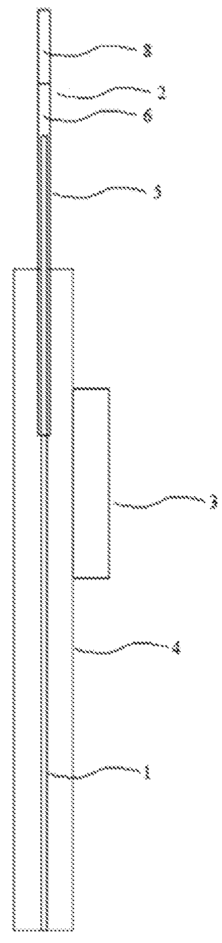
[0211]One embodiment of the present invention provides a device for delivering a substance, as depicted in FIG. 2. The device comprises a delivery unit 5 comprising a mandrel guide (e.g. 2) and a mandrel 1 disposed internally of the mandrel guide (e.g. 2). The mandrel guide (e.g. 2) comprises a proximal length of guide 6 supported by a delivery unit support 4. The mandrel guide (e.g. 2) also comprises a nozzle 8 that is longitudinally fixed relative to the proximal length of guide 6. A delivery controller 3 is operably linked (operable linkage not shown) to the delivery unit 5 through a component other than the nozzle 8 (e.g. proximal to the nozzle such as linked to the mandrel 1 or proximal length of guide 6) to control longitudinal movement of the mandrel 1 relative to the mandrel guide (e.g. 2). Such a configuration allows the nozzle 8 to be fully inserted in tissue when the delivery unit 5 is in position for delivery such that the nozzle does n...

example 3

Device with Conductive Mandrel

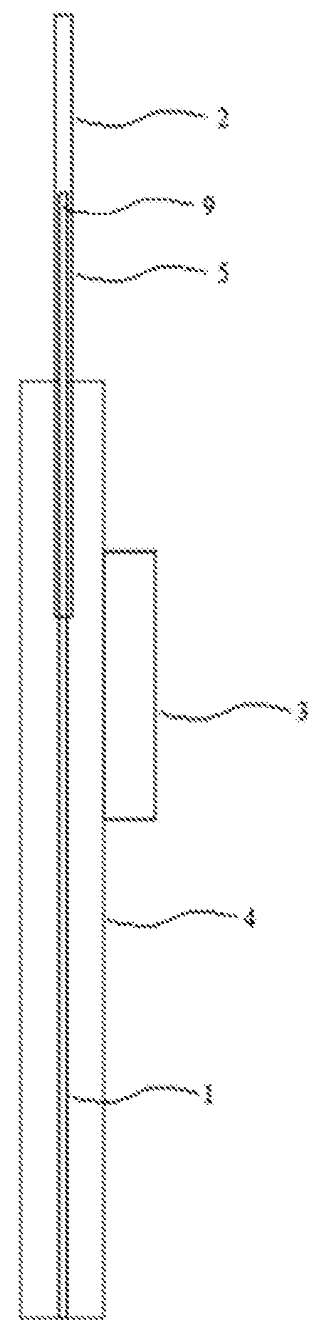
[0212]One embodiment of the present invention provides a device for delivering a substance, as depicted in FIG. 3a. The device comprises a delivery unit 5 comprising a mandrel guide (e.g. 2) and a mandrel 1 disposed internally of the mandrel guide (e.g. 2). The delivery unit is supported by a delivery unit support 4. A delivery controller 3 is operably linked (operably linkage not shown) to the delivery unit 5 to control longitudinal movement of the mandrel 1 relative to the mandrel guide (e.g. 2). The mandrel 1 interfaces with the substance intended for delivery (not shown) at the distal end 9 of the mandrel 1. The mandrel further comprises least one conductive member, such as a tubular member 10 to conduct gas, liquid, or other substances such as fiber optic fibers. As depicted in FIG. 3b, optionally, the mandrel 1 comprises a plurality of tubular members 10 and / or a filler weld 11 to increase the surface area of the interface between the distal end 9...


PUM


Abstract

This invention provides a device for delivering substances such as medical implants and tissues. The device comprises a mandrel and a mandrel guide whereby substances are delivered by retracting the mandrel guide relative to the mandrel. Included among the various embodiments are devices specialized for delivering retinal pigment epithelial (RPE) cells or nanoplates containing RPE cells to the retina, devices with precise control of delivery, devices with specialized mandrels and / or nozzles, and multifunctional devices adapted to provide additional functions such as infusion and / or suction, illumination, and diathermy.

Description

CROSS-REFERENCE TO RELATED APPLICATIONS[0001]This application is a continuation of PCT / US2010 / 060622, filed 16 Dec. 2010, which claims priority to U.S. Provisional 61 / 286,788 filed 16 Dec. 2009, which are hereby incorporated by reference in their entirety.TECHNICAL FIELD[0002]The present invention relates to delivery and extraction devices.BACKGROUND[0003]Medical implantation procedures generally involve the delivery of a desired substance (e.g. tissue, drug, microchip, etc) to a target site in a subject. One type of tool that has found use in certain procedures is the plunger-barrel type device. The use of a plunger-barrel type device for delivery typically involves the steps of loading a barrel with a desired substance, placing the distal end of the barrel at or near the target site in a subject, and ejecting the substance from the barrel by sliding a plunger through the barrel towards the distal end at the target site. Plunger-barrel type devices have also found use in extraction...

Claims


Application Information

Patent Timeline
Patent Type & Authority Patents(United States)
IPC IPC(8): A61F9/00A61B17/34A61M1/12A61F9/007A61M5/142
CPCA61F9/0017A61B17/3468A61F9/00781A61M1/12A61M5/14276A61M60/289A61M60/104A61M5/00A61B2017/00862A61K9/0051A61K35/30A61M37/0069A61M2202/09A61M2210/0612
Inventor HICKINGBOTHAM, DYSONRADTKE, NORMAN
Owner HICKINGBOTHAM DYSON
Why Eureka
Try Eureka