Surface treatment of rubber using low pressure plasma

a technology of plasma and rubber, applied in the field of surface treatment of substances using low pressure plasma, can solve the problems of difficult or impossible separation of bladder from vulcanized tyre, cleaning the inner liner surface using expensive and high energy-consuming processes and polluting cleaning agents, and washing works, so as to save labour and time, the effect of avoiding the use of release agents

Active Publication Date: 2016-07-05
MUNCH CHEM INT
View PDF10 Cites 1 Cited by
  • Summary
  • Abstract
  • Description
  • Claims
  • Application Information

AI Technical Summary

Benefits of technology

[0026]By using bladders treated by the method of the invention tyre manufacturers will avoid the repeated manual process of coating the bladders with release agents at about every fifth tyre produced. Thus the invention saves labour and time, the use of release agents is avoided. And there is no pollution of the working place and the manufacturing machine as well as the environment. The complex processes of removing release agent from the inner lining which may sometimes be unsatisfactory are also avoided.

Problems solved by technology

If no or insufficient release agent is applied to the bladder it may be difficult or impossible to separate the bladder from the vulcanized tyre.
Release agent left on the inside of a tyre may cause problems, in particular if e.g. a substance or part is later to be applied to the inner liner.
Therefore, the surface of the inner liner is cleaned using expensive and high energy consuming processes and polluting cleaning agents.
But even washing works only with certain release agents and then only unsatisfactory.
This is currently only possible if the area to which the foam will be glued is mechanically roughened which may damage the inner liner.
These bumpers are typically made of PP or EPDM, and no other material will adhere well to these materials, and bumpers of these materials can not normally be durably painted.

Method used


Image

  • Surface treatment of rubber using low pressure plasma

Examples


Embodiment Construction

[0028]Throughout this specification the word “comprise” or variations such as “comprises” or “comprising”, will be understood to imply the inclusion of a stated element, integer or step, or group of elements, integers or steps, but not the exclusion of any other element, integer or step, or group of elements, integers or steps.

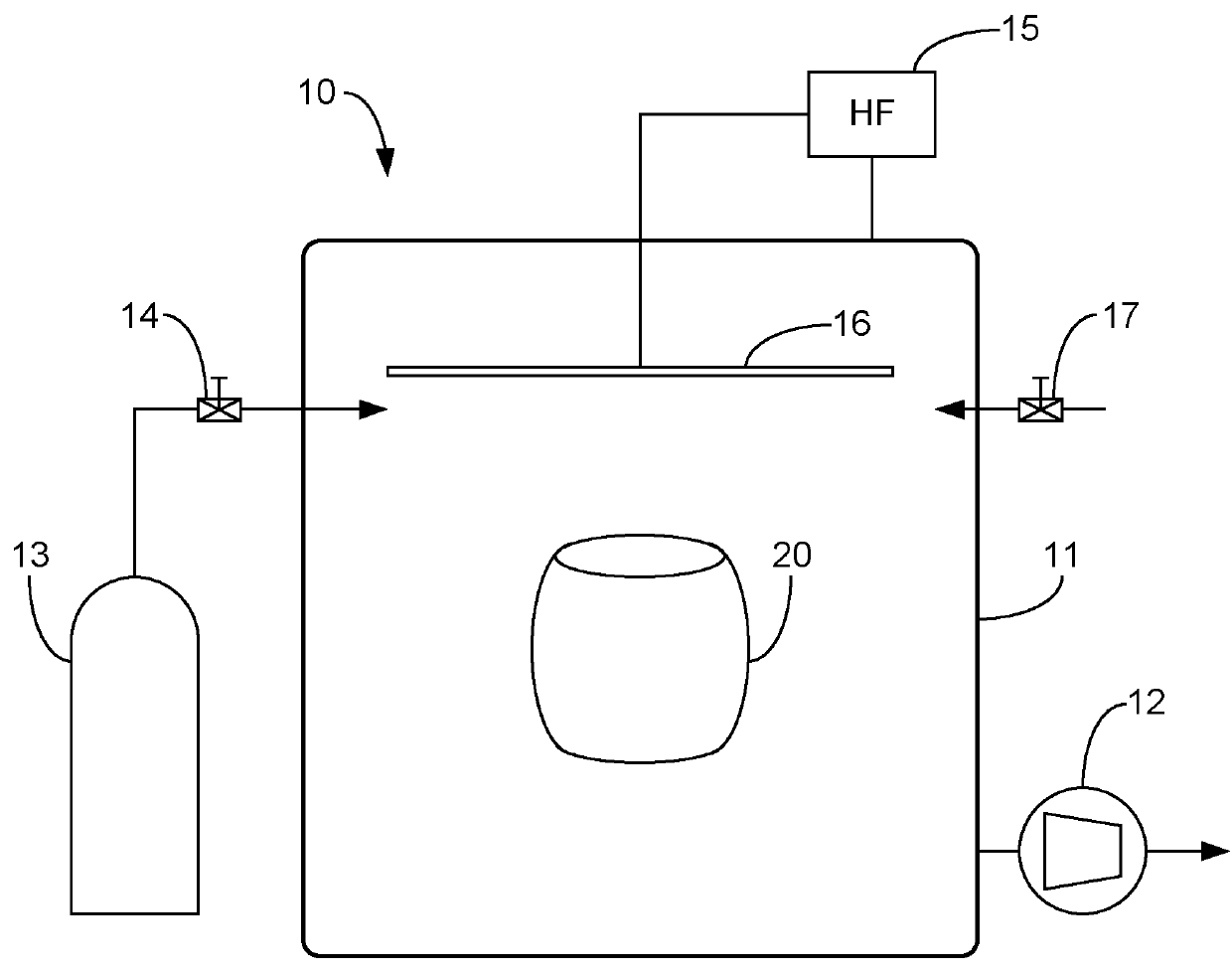
[0029]In the FIGURE is shown a system 10 with an airtight chamber 11 having a volume that is sufficient for receiving one or more objects to be treated. An evacuation pump 12 is coupled to the chamber 11 and can be controlled to evacuate the chamber 11. A gas supply, e.g. in the form of a metal container 13, is provide for supplying a gas that is susceptible of forming a plasma, through a controllable gas inlet valve 14 to the chamber 11. A high frequency generator 15 can be controlled to generate a high frequency electrical signal and to feed the high frequency electrical signal to an electrode 16 inside the chamber 11 so as to cause the gas in the chamber to...


PUM

PropertyMeasurementUnit
pressureaaaaaaaaaa
pressureaaaaaaaaaa
treatment timeaaaaaaaaaa

Abstract

A method of treating a surface of an object comprising a rubber material and in particular a bladder for use in a process for making a vehicle tire. The method comprises subjecting the surface to a gas at a low pressure at which the gas is susceptible of forming plasma, and causing the gas to form plasma. In order to obtain repellent properties of the surface of the rubber material fluorine gas such as tetrafluormethane or hexafluorethane is used. Preferably the treatment is performed until there is obtained a surface layer of the rubber material with properties modified by the treatment having an expected lifetime corresponding to the expected lifetime of the object.

Description

CROSS-REFERENCE TO RELATED APPLICATIONS[0001]This application is a U.S. National Stage of Inernational Application No. PCT / EP2011 / 059333, filed Jun. 7, 2011, which claims the benefit of European Patent Application No. 10167306.9, filed on Jun. 25, 2010, both of which are incorporated herein by reference in their entireties.FIELD OF THE INVENTION[0002]The invention relates to surface treatment of substances using low pressure plasma, and in particular to treatment of surfaces of rubber for modifying the surface in order to obtain certain desired surface properties.BACKGROUND OF THE INVENTION[0003]In the manufacture of all kinds vehicle tyres a tyre blank or “green tyre” comprising several layers of unvulcanized rubber compounds is placed in a metal mould that produces the outer contour i.e. the profile, the sidewall geometry and the tread pattern of the tyre. In order to press the unvulcanized tyre blank into the metal mould contour a bladder is placed inside the green tyre and press...

Claims


Application Information

Patent Timeline
Patent Type & Authority Patents(United States)
IPC IPC(8): B29C41/00B29D30/06B29C59/14B05D1/00C08J7/12
CPCB05D1/62B29C59/14B29D30/0645C08J7/123B29C59/142B29C2791/005B29C2791/006C08J2321/00Y10T428/31938
Inventor RONLAN, ALVIN
Owner MUNCH CHEM INT
Why Eureka
Try Eureka