

Liquid distributor and liquid collector for chromatography columns
a liquid distributor and liquid collector technology, applied in the direction of ion exchangers, separation processes, instruments, etc., can solve the problem of not being able to meet all criteria at the same time, and achieve the effect of improving the equal distribution
Active Publication Date: 2016-07-05
YMC
View PDF29 Cites 3 Cited by
- Summary
- Abstract
- Description
- Claims
- Application Information
AI Technical Summary
Benefits of technology
This patent describes a new liquid distributor and collector, which can be used in chromatography columns. The design allows for efficient distribution of liquid over a large cross section, and can be easily manufactured in a simple process. Compared to conventional chromatography columns, the new design also provides better separation. The use of a frit, made of metal or other materials, can further improve the distribution of the liquid distributor and collector. This new design provides a more flexible and efficient tool for industrial production of chromatography columns.
Problems solved by technology
With an increasing number of openings (>32), it is no longer possible to fulfill all criteria at the same time.
Method used
View moreImage
Smart ImageViewing Examples

Examples
examples
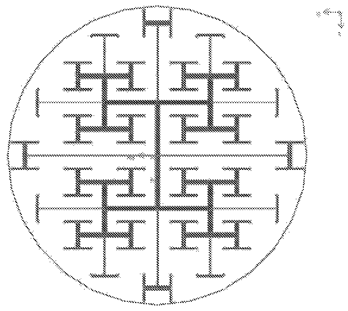
[0032]FIG. 1 shows the side of the liquid distributor and collector facing toward the column packing. 96 equidistant openings which are arranged uniformly over the circular flow cross section can be seen. The openings are circular.
[0033]FIG. 2 shows the side of the liquid distributor and collector facing away from the column packing, with inlet and outlet at the center. The flow channels are shown in symmetrical and asymmetrical T-distributor shape. The openings toward the column packing are each in the tips of the Ts.
Login to View More PUM
| Property | Measurement | Unit |
|---|---|---|
| cross-sectional area | aaaaa | aaaaa |
| cross-sectional area | aaaaa | aaaaa |
| width | aaaaa | aaaaa |
Abstract
The present application relates to a liquid distributor and collector for columns for liquid chromatography with preferably round cross section, which is particularly suitable for columns with large diameter in relation to the packing height.
Description
[0001]This is a 371 of PCT / EP2005 / 009229 filed Aug. 26, 2005 (international filing date).[0002]The present application relates to a liquid distributor and collector for columns for liquid chromatography, which is suitable particularly for columns with large cross-sectional area in relation to the packing height.BACKGROUND OF THE INVENTION[0003]Liquid distributors and collectors are used in column chromatography in order to uniformly distribute and to collect the liquid over the flow cross section. This is a necessary prerequisite to achieve the desired separating performance.[0004]In order to accommodate the amounts of adsorbent required for the purification of the ever greater feed volumes in a column, development in chromatography is in the direction of larger column diameters, since there is an upper limit in the column length owing to the pressure drop and a minimum residence or process time. In order still to enable good separating performances in these columns with large cross...
Claims
Login to View More Application Information
Patent Timeline
 Patent Type & AuthorityPatents(United States)
IPC IPC(8): G01N30/60B01D15/14B01D15/18B01D15/26G01N30/02
CPCG01N30/6017B01D15/14B01D15/18G01N30/02G01N30/603G01N30/6004Y10T29/494
InventorKLEPP, GEORG-HEINRICHBOCKER, SEBASTIANSTRUBE, JOCHENKANSY, HEINZSCHMALE, HENDRIK
OwnerYMC