Detector comprising a transversal optical sensor for detecting a transversal position of a light beam from an object and a longitudinal optical sensor sensing a beam cross-section of the light beam in a sensor region

a transversal optical sensor and transversal technology, applied in the field of detectors, can solve the problems of overlapping volumes, information can be recorded, and the origin of signals becomes unidentifiabl

Active Publication Date: 2016-07-12
BASF SE
View PDF57 Cites 102 Cited by
  • Summary
  • Abstract
  • Description
  • Claims
  • Application Information

AI Technical Summary

Benefits of technology

[0052]The transversal optical sensor may further be adapted to generate the transversal sensor signal in accordance with the electrical currents through the partial electrodes. Thus, a ratio of electric currents through two horizontal partial electrodes may be formed, thereby generating an x-coordinate, and / or a ratio of electric currents through to vertical partial electrodes may be formed, thereby generating a y-coordinate. The detector, preferably the transversal optical sensor and / or the evaluation device, may be adapted to derive the information on the transversal position of the object from at least one ratio of the currents through the partial electrodes. Other ways of generating position coordinates by comparing currents through the partial electrodes are feasible.
[0348]The at least one transversal optical sensor and / or the at least one longitudinal optical sensor may further be encapsulated and / or packaged, in order to provide protection against environmental influences, such as oxygen and / or humidity. Thereby, an increased long-term stability may be provided.

Problems solved by technology

According to their study, the authors could observe that this depth sensor required a settling time of approximately 30 seconds from the time the device was powered until a reliable depth signal was acquired, in particular owing to a large amount of computing power being required for performing this kind of procedure.
A further problem arises when more than one active sensor is employed for acquiring depth information, particularly for extending a measurement range.
As soon as signals which originate from one or more different or identical active sensors overlap, the origin of the signals becomes unidentifiable, so that in the region where the signals overlap no depth information can be recorded.
A similar problem arises when two or more active sensors point towards each other.
Particularly, since the measurement volume of an optical sensor can be described as an approximate cone, a large measurement volume can only be covered by a number of active sensors which, however, results in overlapping volumes and, thus, uncovered regions.
Distance measurements, by contrast, are based in many cases on technically inadequate assumptions such as, for example, the assumption of a specific size of an object in an image evaluation.
Therein, reference is made to the fact that defects or traps may diminish the efficiency of the organic solar cell.

Method used


Image

  • Detector comprising a transversal optical sensor for detecting a transversal position of a light beam from an object and a longitudinal optical sensor sensing a beam cross-section of the light beam in a sensor region
  • Detector comprising a transversal optical sensor for detecting a transversal position of a light beam from an object and a longitudinal optical sensor sensing a beam cross-section of the light beam in a sensor region
  • Detector comprising a transversal optical sensor for detecting a transversal position of a light beam from an object and a longitudinal optical sensor sensing a beam cross-section of the light beam in a sensor region

Examples


Embodiment Construction

Detector

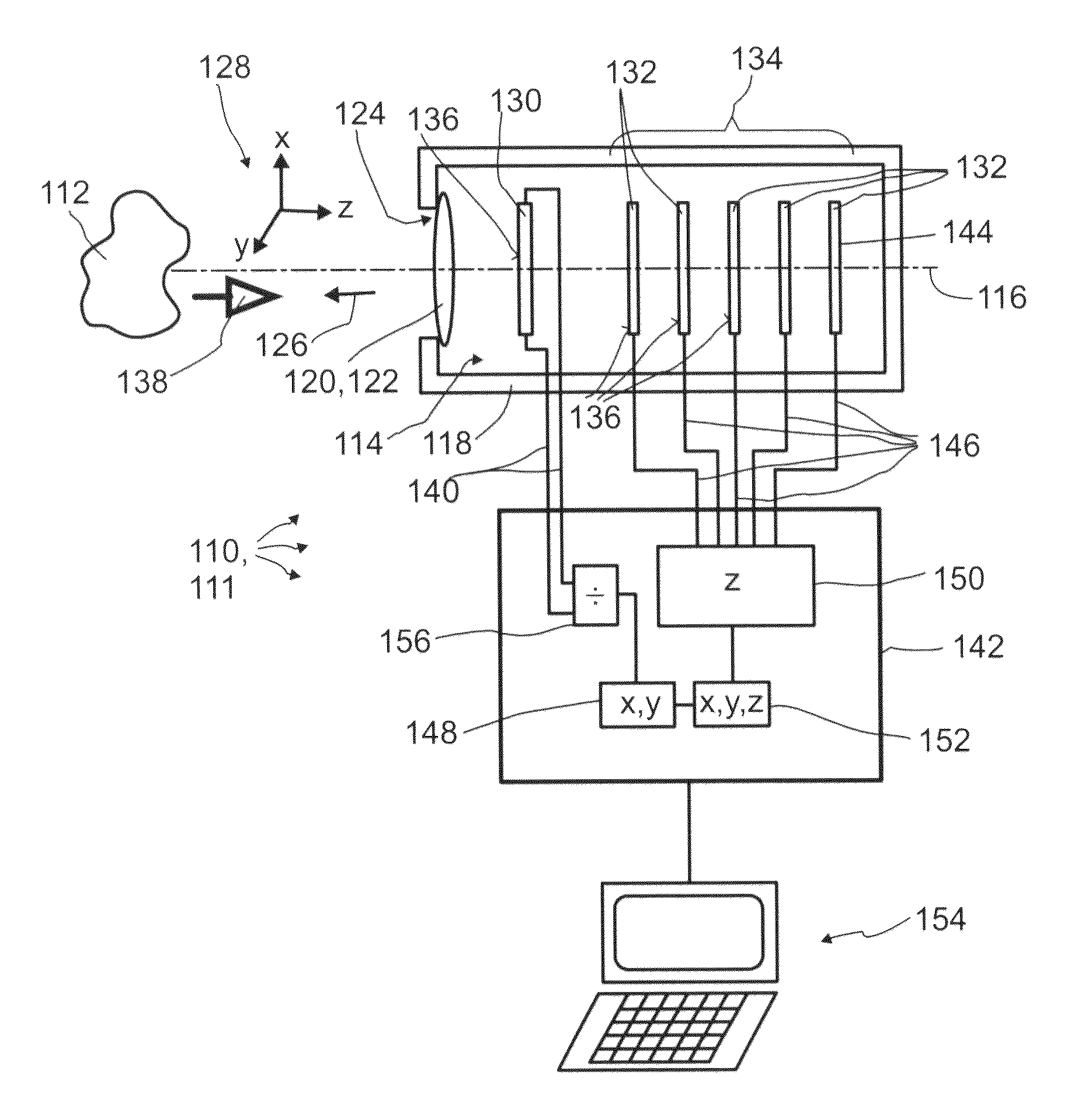
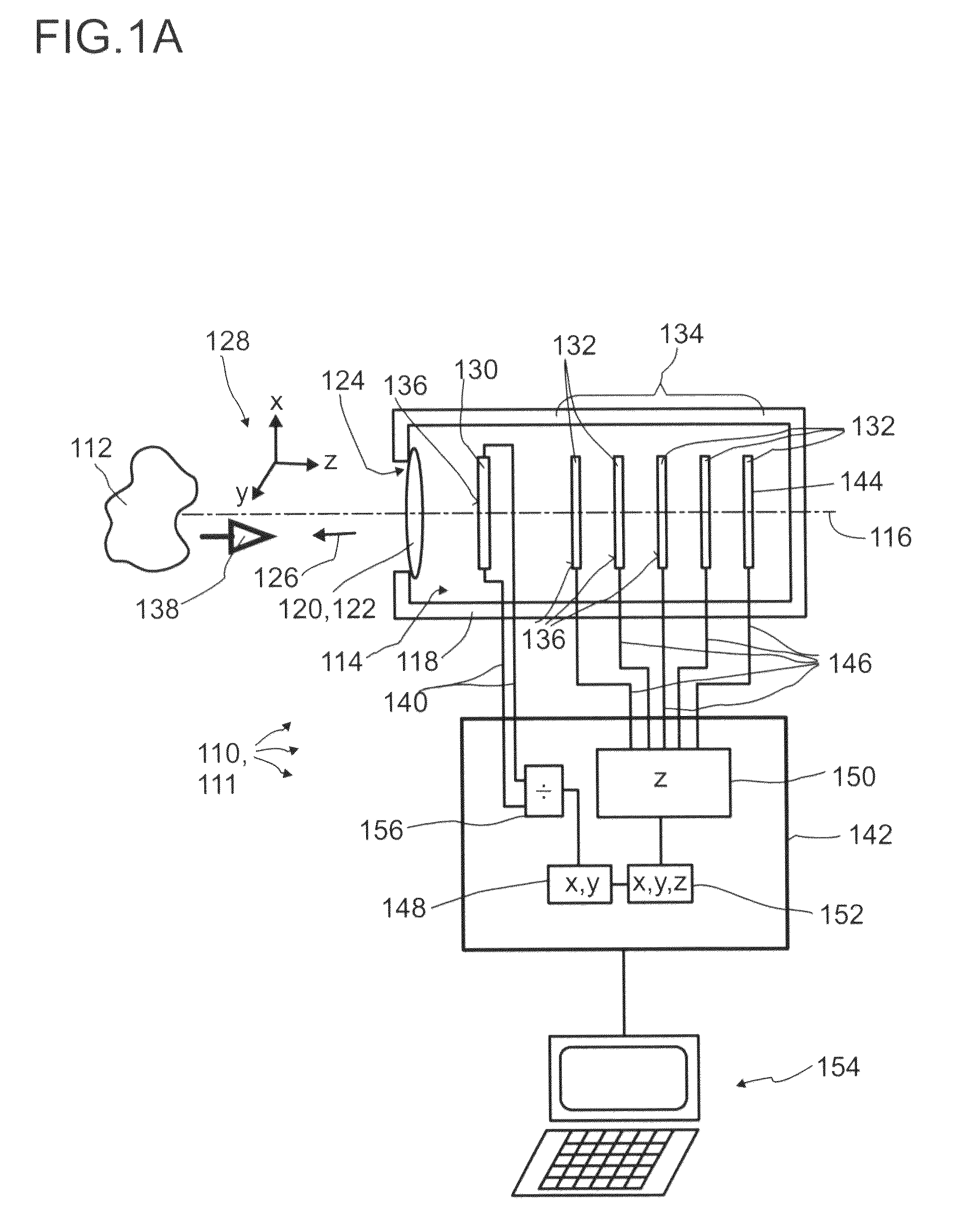
[0466]FIG. 1A illustrates, in a highly schematic illustration, an exemplary embodiment of a detector 110 according to the invention, for determining a position of at least one object 112. The detector 110 preferably may form a camera 111 or may be part of a camera 111. Other embodiments are feasible.

[0467]The detector 110 comprises a plurality of optical sensors 114, which, in the specific embodiment, are all stacked along an optical axis 116 of the detector 110. Specifically, the optical axis 116 may be an axis of symmetry and / or rotation of the setup of the optical sensors 114. The optical sensors 114 may be located inside a housing 118 of the detector 110. Further, at least one transfer device 120 may be comprised, such as one or more optical systems, preferably comprising one or more lenses 122. An opening 124 in the housing 118, which, preferably, is located concentrically with regard to the optical axis 116, preferably defines a direction of view 126 of the detector 11...


PUM


Abstract

A detector (110) for determining a position of at least one object (112) is proposed. The detector (110) comprises:at least one transversal optical sensor (130), the transversal optical sensor (130) being adapted to determine a transversal position of at least one light beam (138) traveling from the object (112) to the detector (110), the transversal position being a position in at least one dimension perpendicular to an optical axis (116) of the detector (110), the transversal optical sensor (130) being adapted to generate at least one transversal sensor signal;at least one longitudinal optical sensor (132), wherein the longitudinal optical sensor (132) has at least one sensor region (136), wherein the longitudinal optical sensor (132) is designed to generate at least one longitudinal sensor signal in a manner dependent on an illumination of the sensor region (136) by the light beam (138), wherein the longitudinal sensor signal, given the same total power of the illumination, is dependent on a beam cross-section of the light beam (138) in the sensor region (136);at least one evaluation device (142), wherein the evaluation device (142) is designed to generate at least one item of information on a transversal position of the object (112) by evaluating the transversal sensor signal and to generate at least one item of information on a longitudinal position of the object (112) by evaluating the longitudinal sensor signal.

Description

FIELD OF THE INVENTION[0001]The invention relates to a detector for determining a position of at least one object. Furthermore, the invention relates to a human-machine interface, an entertainment device, a tracking system and a camera. Furthermore, the invention relates to a method for optically detecting a position of at least one object and to various uses of the detector. Such devices, methods and uses can be employed for example in various areas of daily life, gaming, traffic technology, production technology, security technology, medical technology or in the sciences. Additionally or alternatively, the application may be applied in the field of mapping of spaces, such as for generating maps of one or more rooms, one or more buildings or one or more streets. However, other applications are also possible in principle.PRIOR ART[0002]A large number of optical sensors and photovoltaic devices are known from the prior art. While photovoltaic devices are generally used to convert ele...

Claims


Application Information

Patent Timeline
Patent Type & Authority Patents(United States)
IPC IPC(8): G06M7/00G01S17/89G01S3/781G01C3/06G01S17/66G01V8/00G01J1/20G01S3/786G01S7/481
CPCG01S17/66G01C3/06G01S3/781G01S3/786G01S7/4816G01S17/89G01S17/46G01S5/0249
Inventor BRUDER, INGMARSPILLER, SIMONE CHRISTINATHIEL, ERWINIRLE, STEPHANSEND, ROBERTWONNEBERGER, HENRIKE
Owner BASF SE
Why Eureka
Try Eureka