Stencil buffer data compression

a buffer data and buffer technology, applied in the field ofgraphics processing, can solve the problems of increasing memory bandwidth, power consumption, and number of processing operations, and affecting the memory bandwidth, power consumption, and processing speed of the gpu, so as to reduce the memory bandwidth, reduce the number of compressible sample groups, and improve the efficiency of the processing unit

Active Publication Date: 2016-07-12
NVIDIA CORP
View PDF6 Cites 4 Cited by
  • Summary
  • Abstract
  • Description
  • Claims
  • Application Information

AI Technical Summary

Benefits of technology

[0011]One advantage of the disclosed approach is that a processing unit may compress stencil values across groups of samples where the stencil values vary by more than one. Consequently, the processing unit performs more stencil operations on compressed stencil data compared to conventional processing units that implement one-bit delta compression techniques. Operating on compressed stencil data improves the efficiency of the processing unit compared to operating on uncompressed stencil data. Accordingly, the processing unit reduces memory bandwidth, reduces power consumption, and increases rendering frame rate compared to conventional processing units that implement more restrictive compression techniques.

Problems solved by technology

Performing this quantity of operations negatively impacts the memory bandwidth, power consumption, and processing speed of the GPU.
Because memory bandwidth, acceptable power consumption, and processing capability of GPUs are limited, any increase in memory bandwidth, power consumption, or number of processing operations is generally undesirable.
One limitation of the one-bit delta stencil buffer compression technique is that the number of compressible sample groups may be limited.
Consequently, the GPU that implemented the one-bit delta stencil compression technique would not provide any memory bandwidth, power, or performance advantage for the group compared to a GPU that did not implement any stencil buffer compression.

Method used


Image

  • Stencil buffer data compression
  • Stencil buffer data compression
  • Stencil buffer data compression

Examples


Embodiment Construction

[0020]In the following description, numerous specific details are set forth to provide a more thorough understanding of the present invention. However, it will be apparent to one of skill in the art that the present invention may be practiced without one or more of these specific details.

System Overview

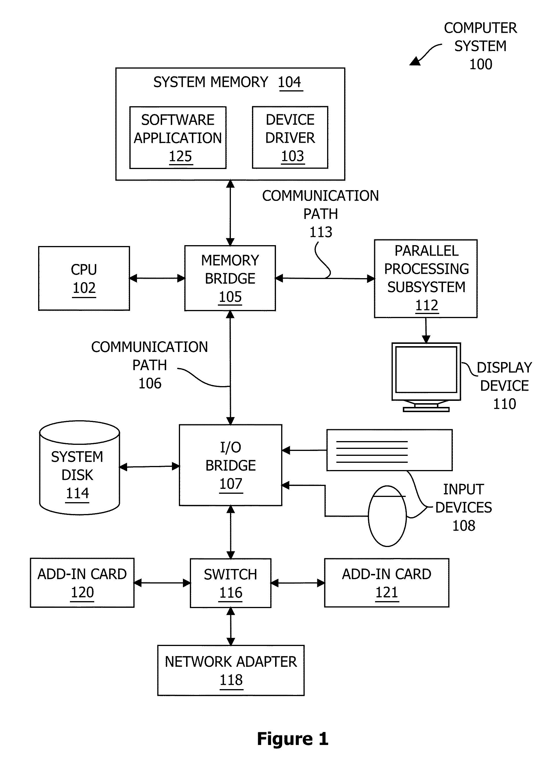
[0021]FIG. 1 is a block diagram illustrating a computer system 100 configured to implement one or more aspects of the present invention. As shown, computer system 100 includes, without limitation, a central processing unit (CPU) 102 and a system memory 104 coupled to a parallel processing subsystem 112 via a memory bridge 105 and a communication path 113. Memory bridge 105 is further coupled to an I / O (input / output) bridge 107 via a communication path 106, and I / O bridge 107 is, in turn, coupled to a switch 116.

[0022]In operation, I / O bridge 107 is configured to receive user input information from input devices 108, such as a keyboard or a mouse, and forward the input information to C...


PUM


Abstract

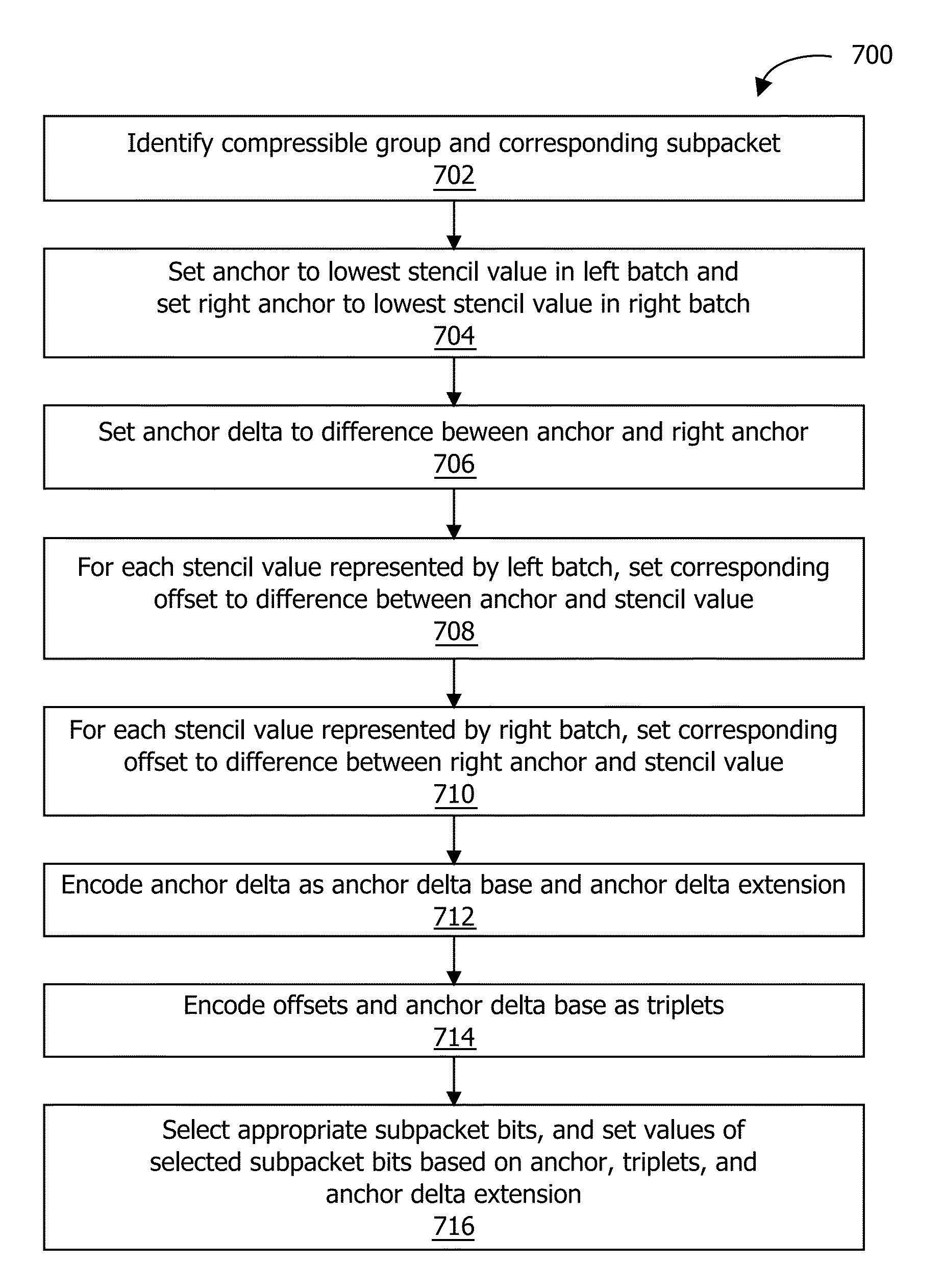
A raster operations (ROP) unit is configured to compress stencil values included in a stencil buffer. The ROP unit divides the stencil values into groups, subdivides each group into two halves, and selects an anchor value for each half. If the difference between each of the stencil values and the corresponding anchor lies within an offset range, and the difference between the two anchors lies within a delta range, then the group is compressible. For a compressible group, the ROP unit encodes the anchor value, offsets from anchors, and an anchor delta. This encoding enables the ROP unit to operate on the compressed group instead of the uncompressed stencil values, reducing the number of memory and computational operations associated with the stencil values. Consequently, the ROP unit reduces memory bandwidth use, reduces power consumption, and increases rendering rate compared to conventional ROP units that implement less flexible compression techniques.

Description

BACKGROUND OF THE INVENTION[0001]1. Field of the Invention[0002]Embodiments of the present invention relate generally to graphics processing and, more specifically, to stencil buffer data compression.[0003]2. Description of the Related Art[0004]Some conventional graphics processing units (GPUs) include different processing engines configured to operate in parallel with one another to implement a graphics processing pipeline. A graphics processing pipeline is the collection of processing steps performed to transform 3-D scene descriptions into rendered 2-D images. When a given processing engine finishes processing data, that processing engine may copy the processed data from local memory to a memory that is shared between the different processing engines within the GPU. Other processing engines may then access the processed data and then perform additional processing operations with that data. One type of data structure used in a graphics processing pipeline to allow different proces...

Claims


Application Information

Patent Timeline
Patent Type & Authority Patents(United States)
IPC IPC(8): G06T9/00G06T1/60G06T15/40H04N19/593G06T15/00H04N19/436
CPCG06T1/60G06T15/005H04N19/436H04N19/593
Inventor AMSINCK, CHRISTIANSCHNEIDER, BENGT-OLAFBOLZ, JEFFREY A.
Owner NVIDIA CORP
Why Eureka
Try Eureka