Hydraulic valve for cam phaser

a technology of cam phaser and hydraulic valve, which is applied in the direction of valve arrangement, machines/engines, mechanical equipment, etc., can solve the problems that the hydraulic valve cannot perform its function anymore, the flow path of the supply connection is blocked, etc., and achieves the effect of simple and quick assembly, simple and fast configuration of the check element, and less wear of components

Active Publication Date: 2016-07-19
HILITE GERMANY
View PDF6 Cites 7 Cited by
  • Summary
  • Abstract
  • Description
  • Claims
  • Application Information

AI Technical Summary

Benefits of technology

[0009]Thus, it is an object of the present invention to provide a hydraulic valve for a cam phaser which assures safe closure and sufficient supply for the hydraulic valve at low camshaft speeds and also at high camshaft speeds and which has a simple and cost effective configuration.

Problems solved by technology

Furthermore a check valve is configured in a flow path of the supply connection so that the hydraulic fluid can flow through the supply connection into the valve housing or into the valve piston, however, so that an exit of the hydraulic fluid through the flow path of the supply connection is blocked.
Chips that reach the valve housing can on the one hand side impede movability of the valve piston, on the other hand side they can block the channels and the channel system so that the hydraulic valve cannot perform its function any more.

Method used


Image

  • Hydraulic valve for cam phaser
  • Hydraulic valve for cam phaser
  • Hydraulic valve for cam phaser

Examples


Embodiment Construction

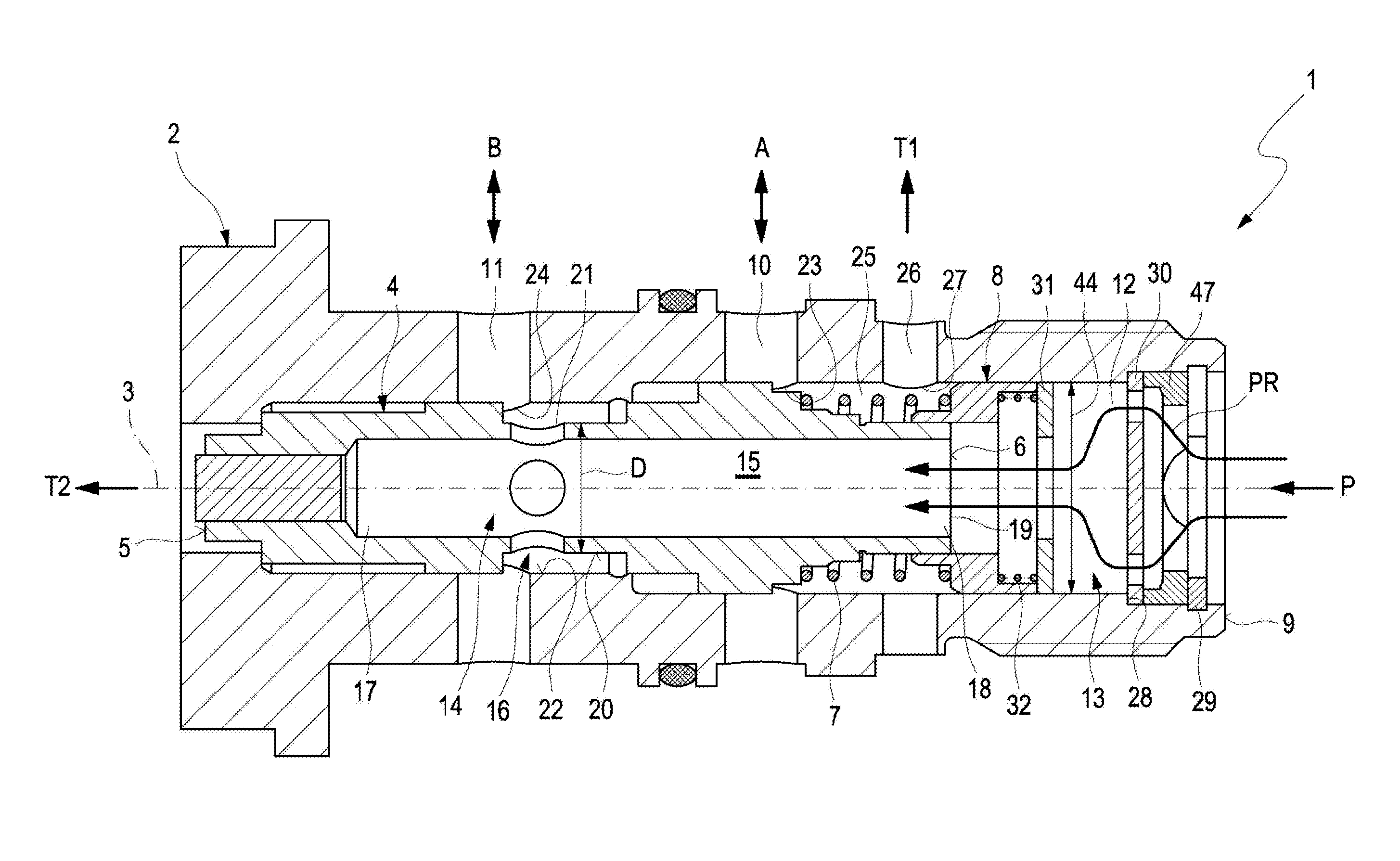
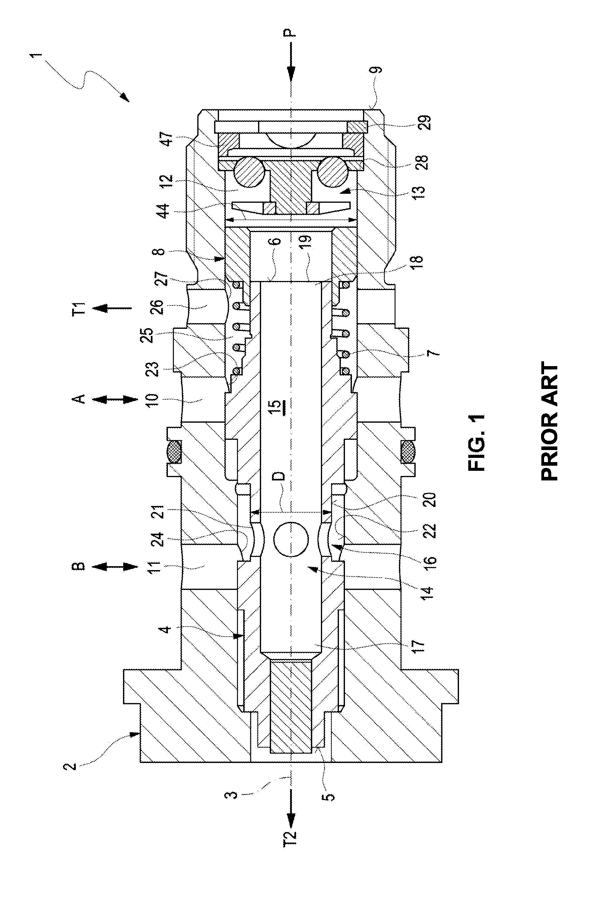
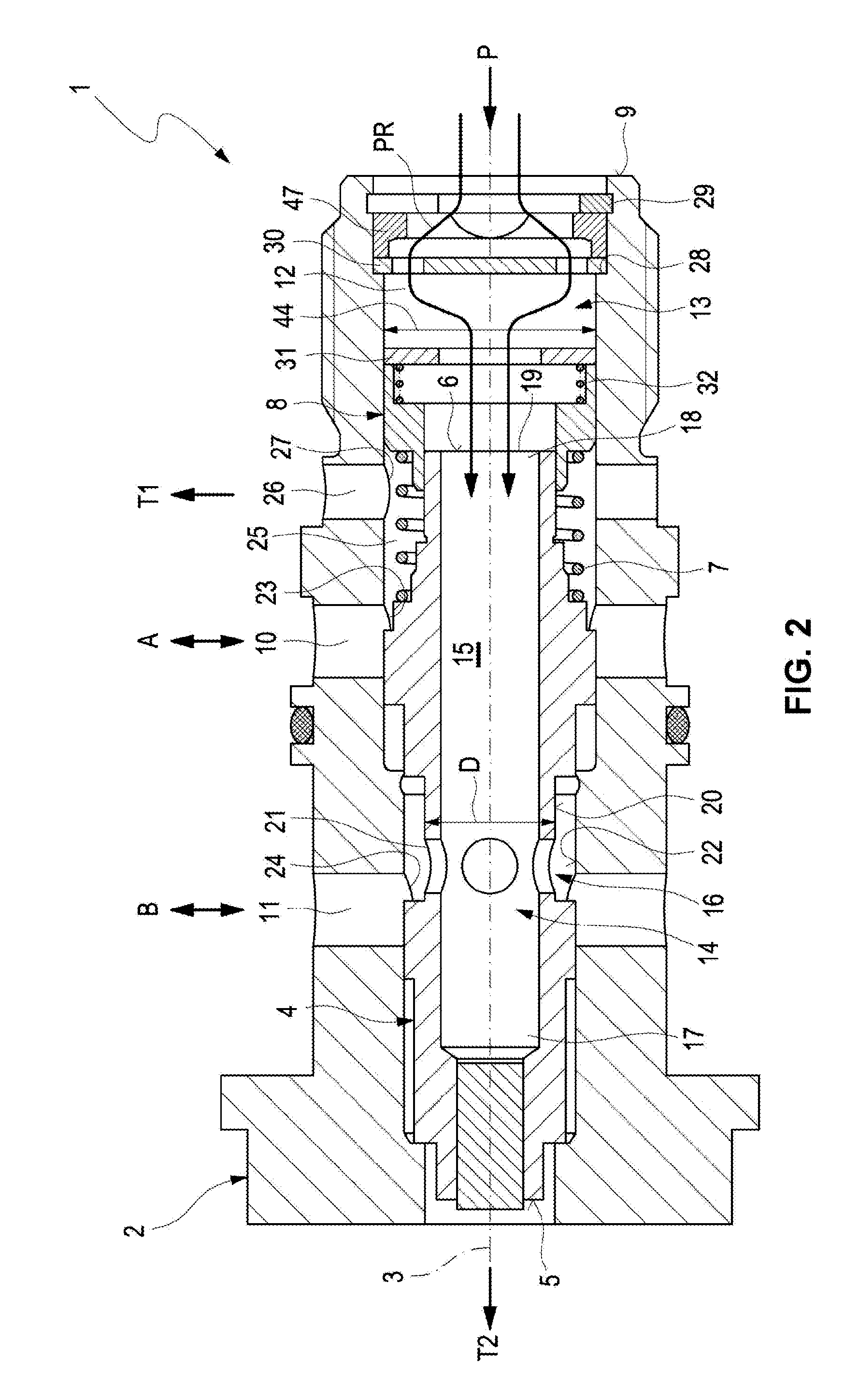
[0035]A cam phaser that is not illustrated in more detail facilitates changing opening and closing times of gas control valves of an internal combustion engine which is not illustrated in more detail. Thus, the cam phaser according to the invention continuously adjusts a relative angular position of a cam shaft of the internal combustion engine relative to a crank shaft of the internal combustion engine wherein the cam shaft and the crank shaft are not illustrated in more detail and wherein the cam shaft is not rotated relative to the crank shaft.

[0036]Rotating the cam shaft moves the opening and closing times of the gas control valves so that the internal combustion engine produces optimum power at a respective speed. Controlling the cam phaser is typically provided by an electronic control unit which controls an inflow and an outflow of hydraulic fluid in pressure chambers provided in the cam phaser based on parameters of the internal combustion engine. A hydraulic valve 1 control...


PUM


Abstract

A hydraulic valve for a cam phaser including a valve housing with a longitudinal axis and a valve piston that is axially moveable along the longitudinal axis, wherein the valve piston opens and closes a first operating connection of the valve housing and a second operating connection of the valve housing, wherein the first operating connection and the second operating connection are axially offset from one another; and a supply connection of the valve housing which is used for supplying the hydraulic valve with a hydraulic fluid fed by a feed device, wherein the hydraulic valve is configured to be flowed through by the hydraulic fluid on different paths controlled by a flow permeable channel system of the valve piston, and wherein a check valve opening and closing an inflow channel is arranged in the hydraulic valve in the inflow channel of the valve housing.

Description

RELATED APPLICATIONS[0001]This applications claims priority from and incorporates by reference German patent application 10 2014 102 617.9 filed on Feb. 27, 2014.BACKGROUND OF THE INVENTION[0002]The present invention relates to a hydraulic valve for a cam phaser.[0003]Hydraulic valves for cam phasers in general are well known. The hydraulic valve includes a flowable valve piston which is received axially moveable in a valve housing of the hydraulic valve. The valve housing is configured with flowable channels so that a hydraulic fluid can flow through these channels and can flow in and out of the valve housing on different flow paths through a channel system configured in the valve piston. Typically the valve housing includes a flowable first operating connection, a flowable second operating connection and a flowable supply connection. The first operating connection and the second operating connection are connected with the cam phaser and the hydraulic fluid is feedable into the hyd...

Claims


Application Information

Patent Timeline
Patent Type & Authority Patents(United States)
IPC IPC(8): F01L1/34F01L1/344
CPCF01L1/3442F01L2001/34423F01L2001/34426
Inventor GRUBER, ERIKOPPEL, MICHAELGOLL, JUERGEN
Owner HILITE GERMANY
Why Eureka
Try Eureka