Load transducer and force measurement assembly using the same

Active Publication Date: 2016-08-02
BERTEC
View PDF62 Cites 55 Cited by
  • Summary
  • Abstract
  • Description
  • Claims
  • Application Information

AI Technical Summary

Benefits of technology

[0073]It should be understood that the appended drawings are not necessarily to scale, presenting a somewhat simplified representation of various preferred features illustrative of the basic principles of the invention. The specific design features of the load transducers as disclosed herein, including, for example, specific dimensions, orientations, locations, and shapes of the various components, will be determined in part by the particular intended application and use environment. Certain features of the illustrated embodiments have

Problems solved by technology

These custom load transducers significantly increase the material costs associated with the fabrication of a force plate.
Also, conventional load transducers often span the f

Method used


Image

  • Load transducer and force measurement assembly using the same
  • Load transducer and force measurement assembly using the same
  • Load transducer and force measurement assembly using the same

Examples


first embodiment

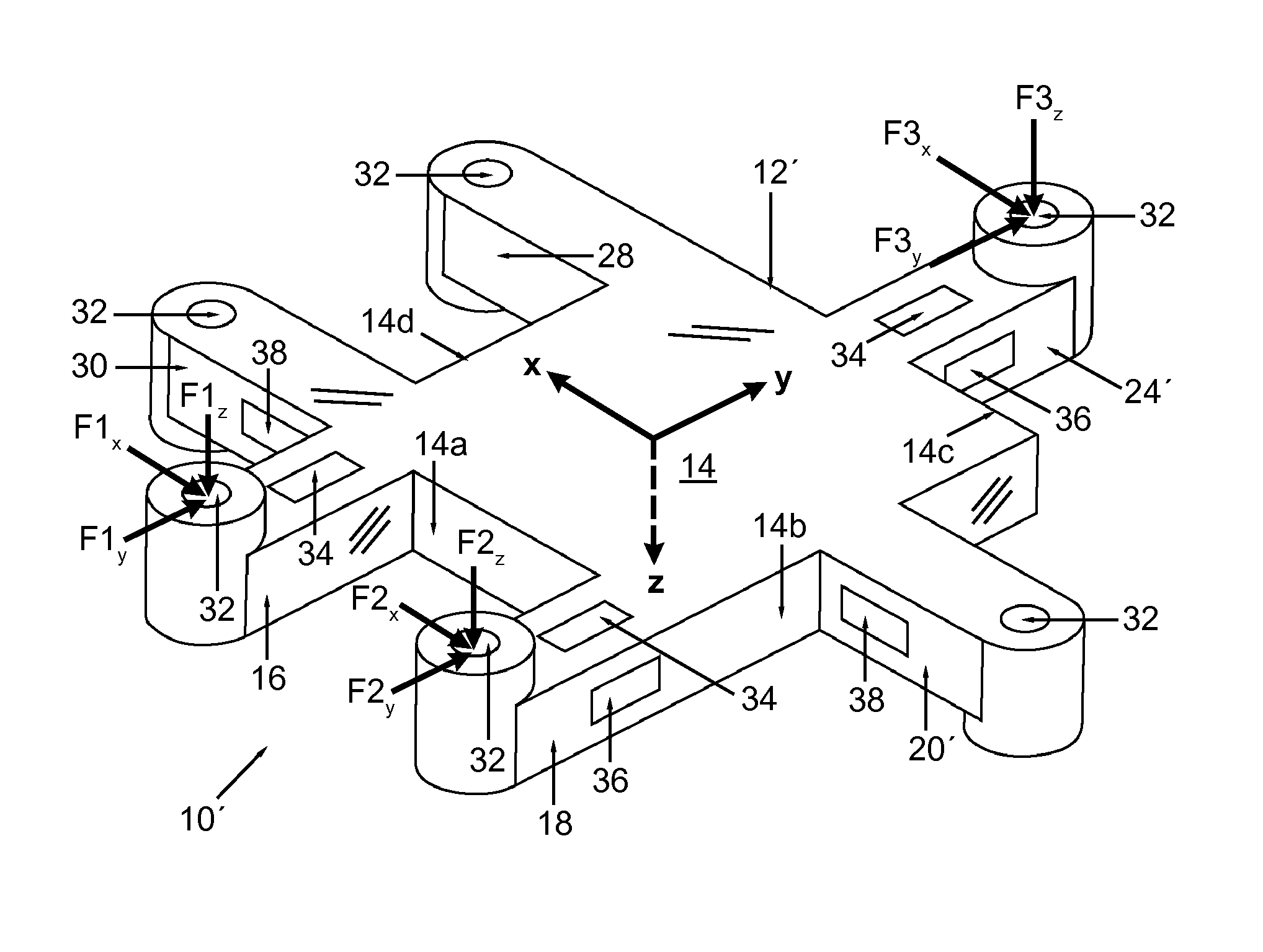
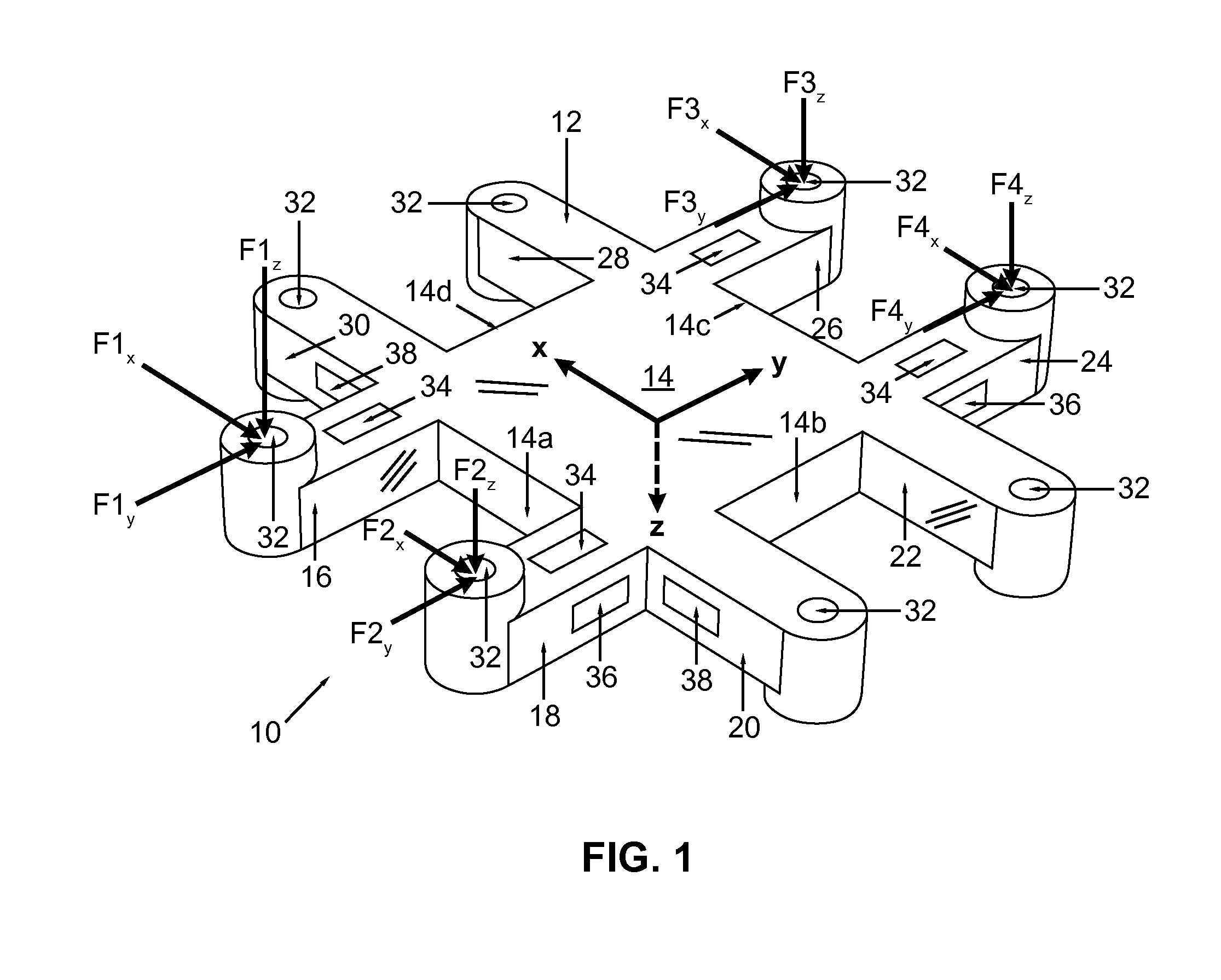
[0035]FIG. 1 is a perspective view of a low profile load transducer, according to the invention;

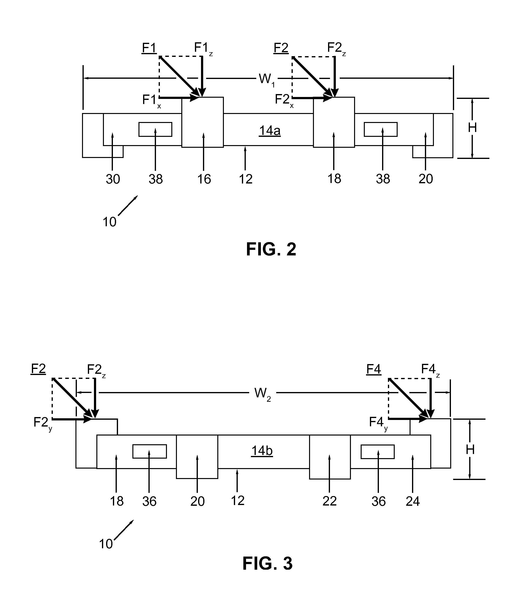
[0036]FIG. 2 is a first side view of the low profile load transducer of FIG. 1, according to the first embodiment of the invention;

[0037]FIG. 3 is a second side view of the low profile load transducer of FIG. 1, according to the first embodiment of the invention;

[0038]FIG. 4 is a top view of the low profile load transducer of FIG. 1, according to the first embodiment of the invention;

[0039]FIG. 5 is a block diagram illustrating data manipulation operations carried out by the load transducer data processing system, according to an embodiment of the invention;

second embodiment

[0040]FIG. 6 is a perspective view of a low profile load transducer, according to the invention;

[0041]FIG. 7 is a first side view of the low profile load transducer of FIG. 6, according to the second embodiment of the invention;

[0042]FIG. 8 is a second side view of the low profile load transducer of FIG. 6, according to the second embodiment of the invention;

[0043]FIG. 9 is a top view of the low profile load transducer of FIG. 6, according to the second embodiment of the invention;

third embodiment

[0044]FIG. 10 is a perspective view of a low profile load transducer, according to the invention;

[0045]FIG. 11 is a first side view of the low profile load transducer of FIG. 10, according to the third embodiment of the invention;

[0046]FIG. 12 is a second side view of the low profile load transducer of FIG. 10, according to the third embodiment of the invention;

[0047]FIG. 13 is a top view of the low profile load transducer of FIG. 10, according to the third embodiment of the invention;

[0048]FIG. 14 is a bottom view of the low profile load transducer of FIG. 10, according to the third embodiment of the invention;


PUM


Abstract

A load transducer is disclosed herein. The load transducer includes a plurality of beam portions connected to one another in succession, the plurality of beam portions being arranged in a circumscribing pattern whereby a central one of the plurality of beam portions is at least partially circumscribed by one or more outer ones of the plurality of beam portions; and at least one load cell disposed on one of the plurality of beam portions, the at least one load cell configured to measure at least one force or moment component of a load applied to the load transducer. A force measurement assembly including a plurality of load transducers with beam portions arranged in a circumscribing pattern is also disclosed herein.

Description

CROSS-REFERENCE TO RELATED APPLICATIONS[0001]This is a continuation-in-part of U.S. Nonprovisional patent application Ser. No. 14 / 158,809, entitled “Low Profile Load Transducer”, filed on Jan. 18, 2014, and further claims the benefit of U.S. Provisional Patent Application No. 61 / 887,357, entitled “Low Profile Load Transducer”, filed on Oct. 5, 2013, the disclosure of each of which is hereby incorporated by reference as if set forth in their entirety herein.STATEMENT REGARDING FEDERALLY SPONSORED RESEARCH OR DEVELOPMENT[0002]Not Applicable.NAMES OF THE PARTIES TO A JOINT RESEARCH AGREEMENT[0003]Not Applicable.INCORPORATION BY REFERENCE OF MATERIAL SUBMITTED ON A COMPACT DISK[0004]Not Applicable.BACKGROUND OF THE INVENTION[0005]1. Field of the Invention[0006]The field of the invention relates to multi-component load transducers utilizing multiple strain gage load channels for precise measurement of forces and moments and, more particularly, to beam-style load cells requiring an overal...

Claims


Application Information

Patent Timeline
IPC IPC(8): G01N3/24G01L5/16G01L1/22G01L5/10
CPCG01L1/2206G01L5/161G01L1/22G01L5/107G01L5/1627
Inventor BERME, NECIPHOFFMAN, BENJAMIN ROBERT
Owner BERTEC
Why Eureka
Try Eureka