Optical cloaking system

Inactive Publication Date: 2016-08-02
LU WEIMIN
View PDF7 Cites 37 Cited by
  • Summary
  • Abstract
  • Description
  • Claims
  • Application Information

AI Technical Summary

Benefits of technology

[0017]The optical cloaking system according to the second aspect is very advantageous because the background behind the object appears stereo-displayed with almost no image distortion to the observer. With such arrangement the first optical device bends and compresses the incident light to pass around the object in the direction parallel to the incident light, and then the second optical device, symmetrically arranged relative to the first on the opposite side of the object, decompresses and bends the light such that the light passing from the second optical device is returned to the original beam width and direction of the incident light. Hence, the background image is viewed by an observer substantially wit

Problems solved by technology

However, such an illusion is highly limited in its practical applications, e.g., due to the need for the second mirror being hidden in a ceiling or the like.
Thus, such a trick is not easily adapted to different situations or settings because the second mirror must be attached somewhere located remotely away from the object itself.
Again, there are known disadvantages with such projection-type camouflaging.
Further, the image being projected on the object or onto the screen is projected in two-dimensions and as such does not have the stereo-feeling/effect when seen by human eyes.
However, with such a method, the materials being used are not common optical materials and as such are difficult to develop and are relatively expensive.
However, materials with a negative refractive index do not occur in any natural material and the known artificially created metamaterials

Method used


Image

  • Optical cloaking system
  • Optical cloaking system
  • Optical cloaking system

Examples


Embodiment Construction

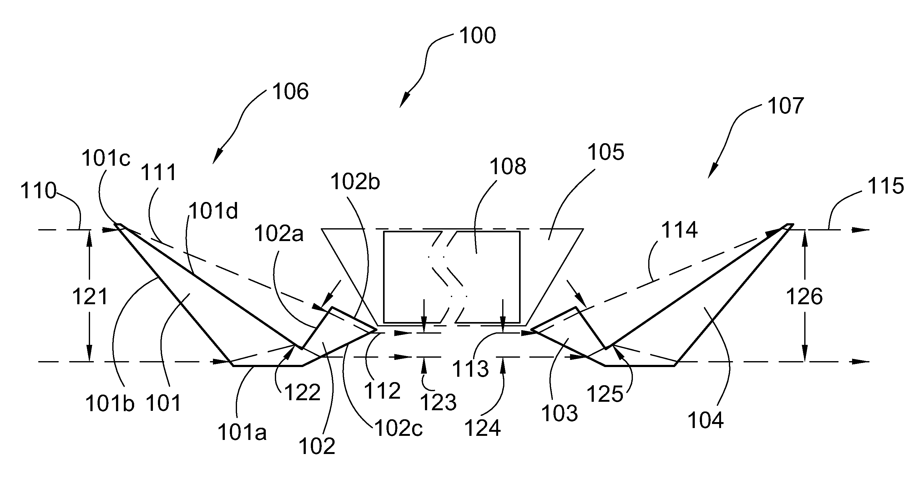
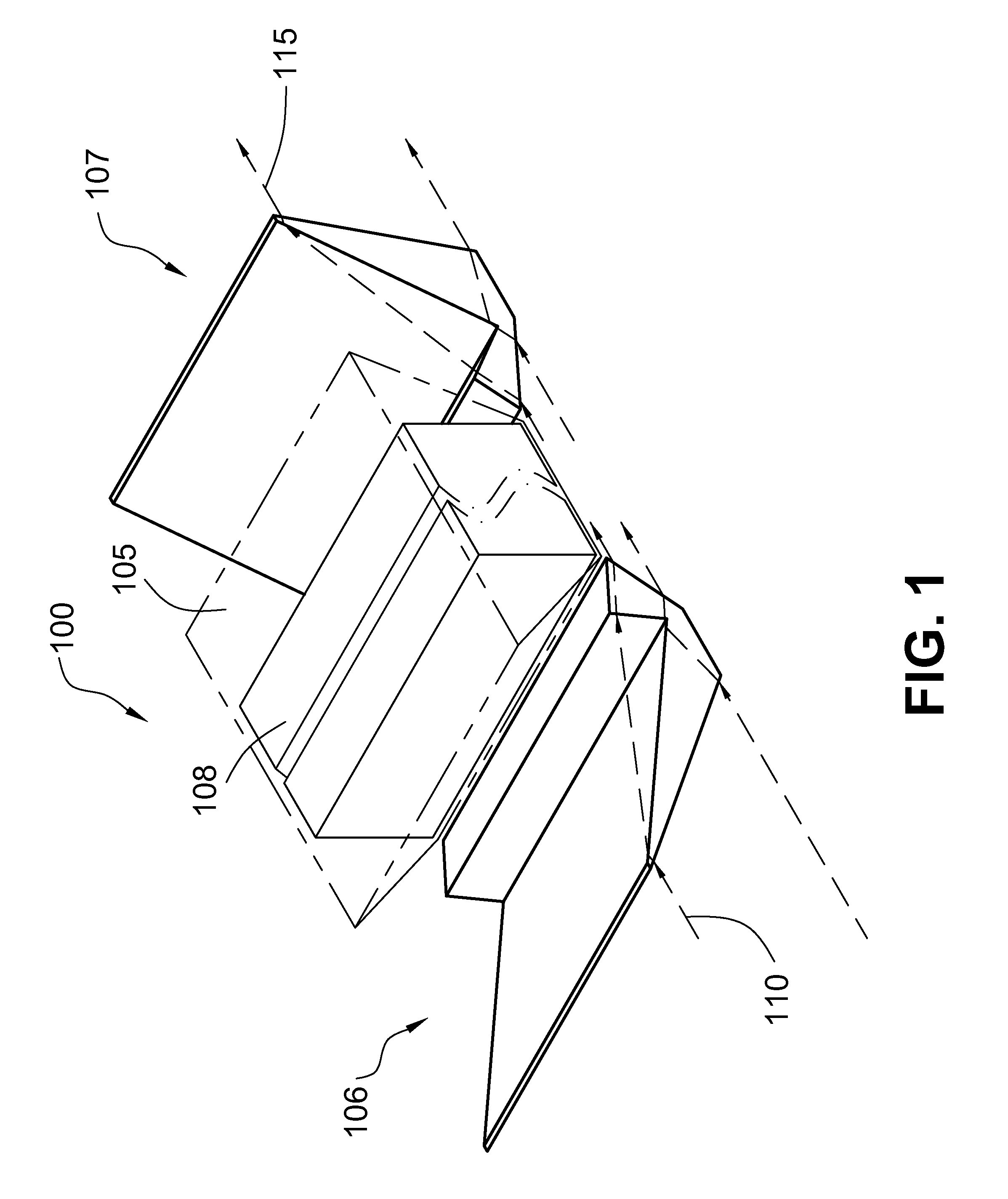
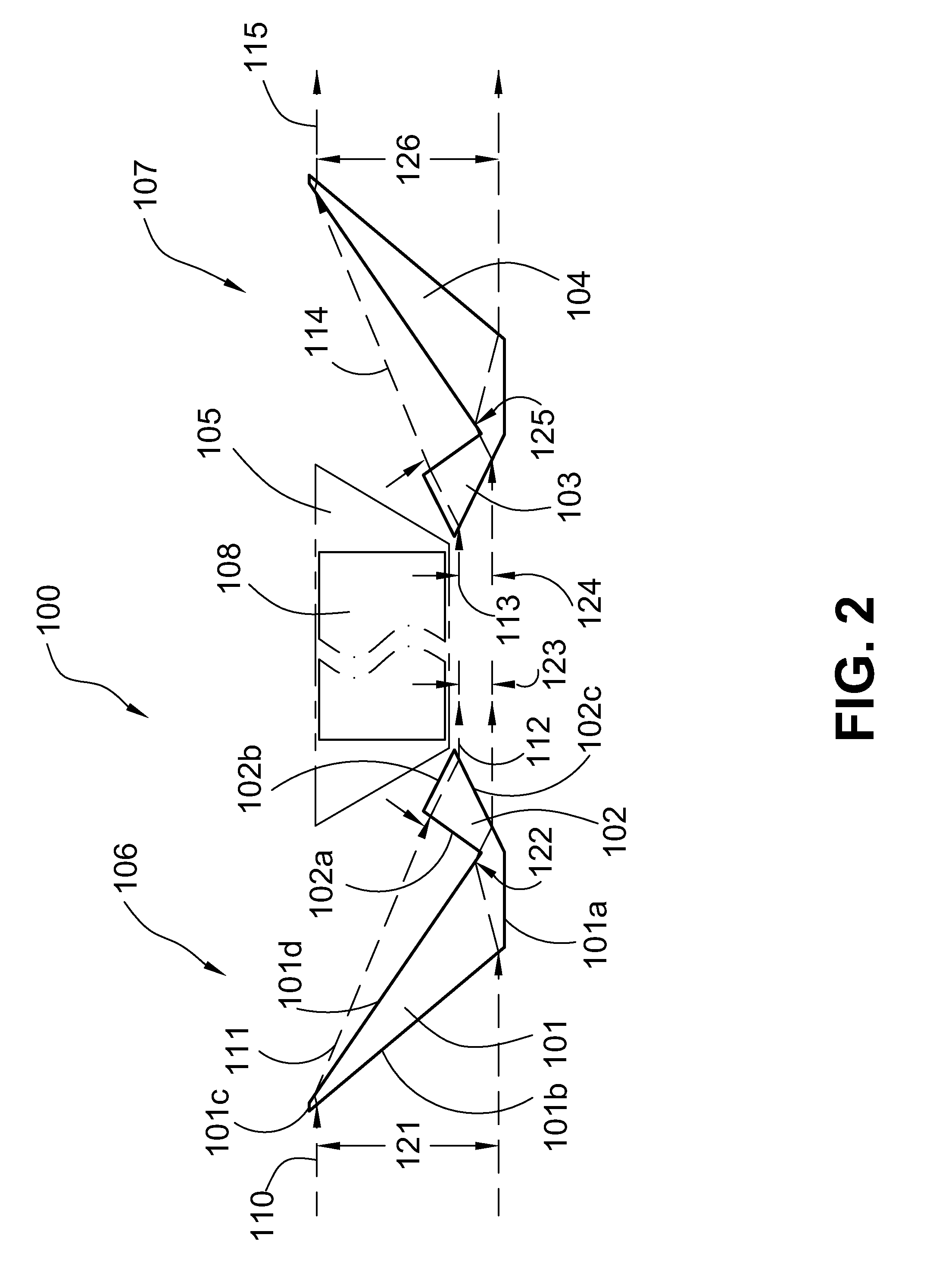
[0039]A number of selected illustrative embodiments of the invention will now be described in some detail, with reference to the drawings. It should be understood that only structures considered necessary for clarifying the present invention are described herein. Other conventional structures, and those of ancillary and auxiliary components of the system, are known and understood by those skilled in the art. These illustrative embodiments are optical cloaking systems and various components of such systems.

[0040]Referring now to the FIGS. 1 and 2, there is shown an optical cloaking system according to a first illustrative embodiment of the present invention, generally denoted by reference numeral 100, comprising a first optical device 106 and a second optical device 107 which has a mirror image or symmetrical structure to that of the first optical device 106, with the two devices 106, 107 disposed symmetrically on opposite sides of an object cavity or cloaking space 105 in which an o...


PUM


Abstract

An optical cloaking system which optically cloaks/hides an object in the visible light spectrum such that the object appears invisible, while permitting a background behind the object to be viewed substantially without distortion. The system includes at least one optical device manufactured using common optical materials in the form of prisms, lenses, mirrors, and the like, which is placed between an observer an the object to be cloaked, and the optical device bends and/or compresses light such that the light passes around a cloaked space in which an object is disposed, and the observer viewing a larger space including the cloaked space will not see the object, but will see a background behind the object in full view substantially undistorted in relation to the rest of the larger space.

Description

CROSS REFERENCE TO RELATED APPLICATIONS[0001]The present application claims priority from U.S. Provisional Patent Application 61 / 646,570. The entire disclosure of this prior application is incorporated herein by reference.BACKGROUND OF THE INVENTION[0002]1. Field of the Invention[0003]The present invention relates to an optical cloaking system, and in particular, to an optical cloaking system which can optically cloak / hide objects in the visible light spectrum such that the objects appear invisible, and which can be efficiently and practically manufactured using common optical materials in the form of prisms, lenses, mirrors, and the like to. Such optical cloaking system bends and / or compresses light such that, within the system, the light passes around a cloaked space in which an object is disposed, and a person viewing a larger space including the cloaked space will not see the object, but in certain embodiments will see a background behind the object in full view substantially un...

Claims


Application Information

Patent Timeline
IPC IPC(8): G02B27/00G02B5/04
CPCG02B27/00G02B5/04G02B27/0075F41H3/00G02B13/0095G02B17/006G02B17/023G02B17/045G02B17/0844G02B17/086
Inventor LU, WEIMIN
Owner LU WEIMIN
Why Eureka
Try Eureka