
Communication terminal and method for controlling data communication

a communication terminal and data communication technology, applied in the field of communication technology, can solve the problems of gps interference gps, bt and wlan cannot operate normally, etc., and achieve the effect of reducing the interference between the communication modules on the terminal

Active Publication Date: 2016-08-02
LENOVO SOFTWARE +1
View PDF8 Cites 2 Cited by
  • Summary
  • Abstract
  • Description
  • Claims
  • Application Information

AI Technical Summary

Benefits of technology

[0005]A communication terminal and a method for controlling data communication are provided by embodiments of the present invention, thus signal interferences between the communication modules on the terminal are reduced.
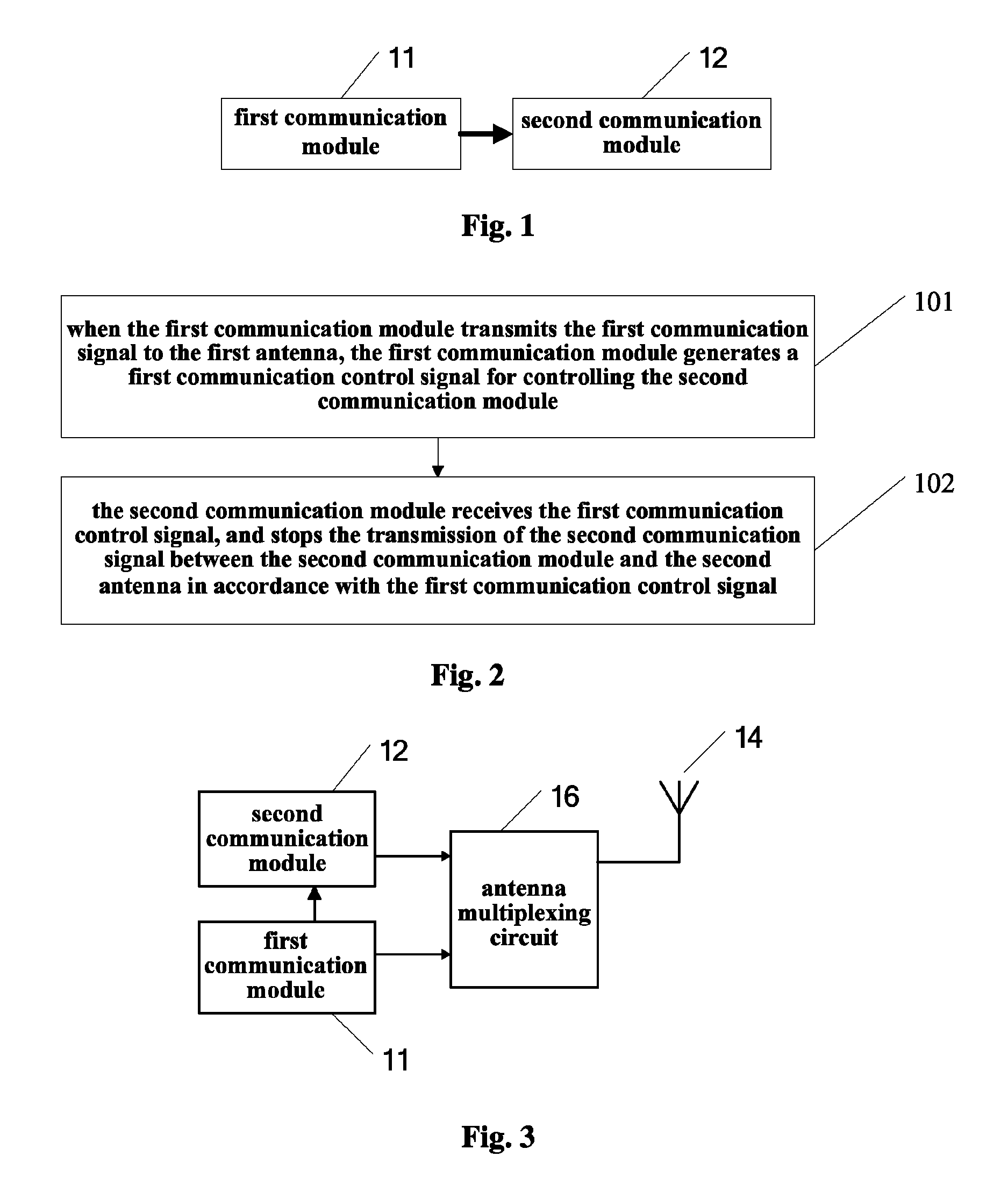
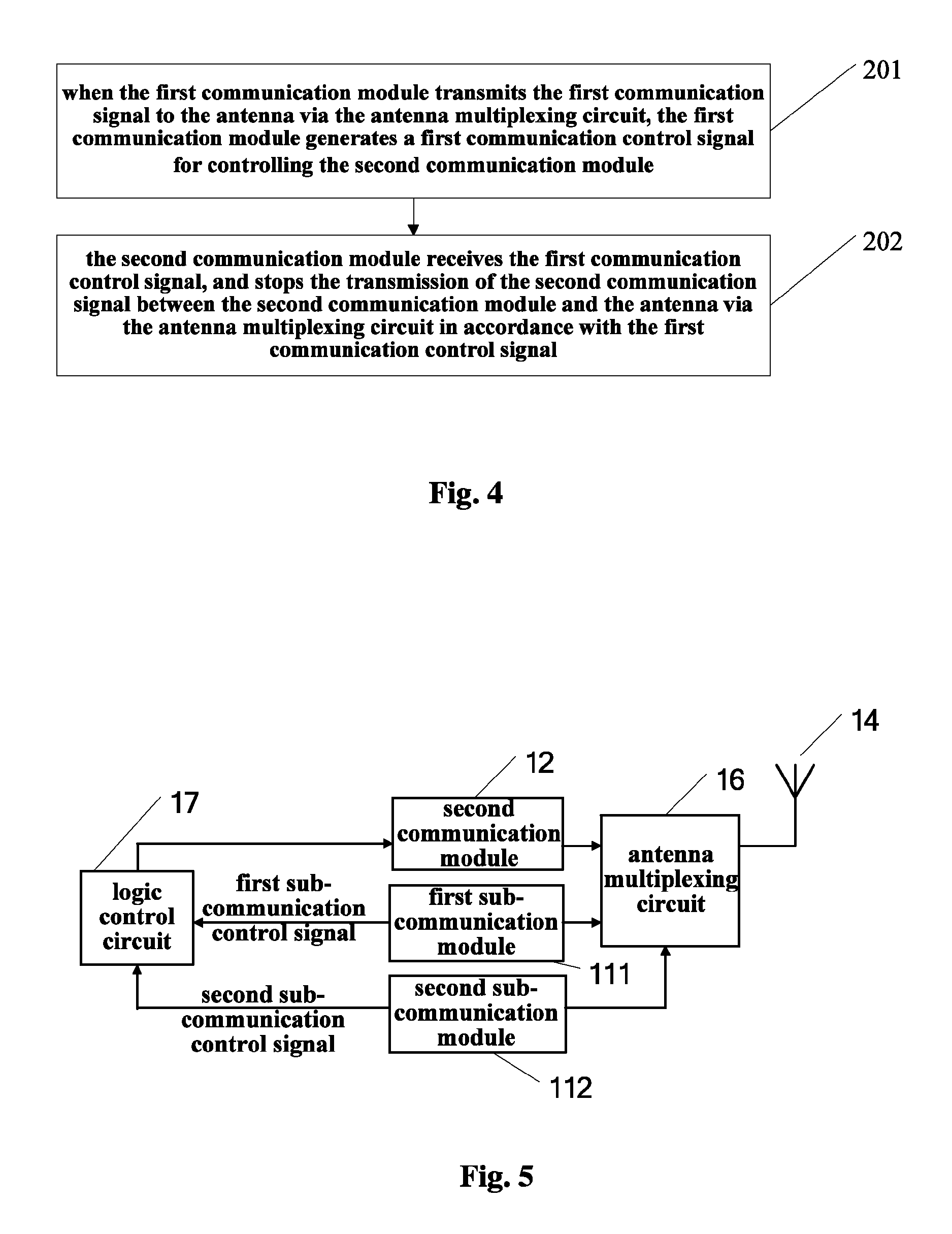
[0023]In the embodiments of the present invention described in the above solutions, the first communication module transmits the first communication control signal to the second communication module, so that when the first communication module transmits the first communication signal, the second communication module stops the transmission of the second communication signal, that is, the respective signals of the first communication module and the second communication module are controlled to be transmitted in different times, thus signal interferences between the communication modules on the terminal are reduced.

Problems solved by technology

Therefore, during the transmission of the BT / WLAN, the input of the GPS LNA becomes bigger so that the GPS LNA enters a saturated zone, and thus the signal of the GPS is interfered and the GPS can not operate normally.
On the other hand, the GSM (Global System for Mobile Communications) on the terminal also has a large transmitting power, and when a GSM signal is transmitted, signals of the GPS, BT and WLAN on the terminal are interfered and thus the GPS, BT and WLAN can not operate normally.

Method used


Image

  • Communication terminal and method for controlling data communication
  • Communication terminal and method for controlling data communication
  • Communication terminal and method for controlling data communication

Examples


first embodiment

[0049]The First Embodiment

[0050]Exemplarily, as shown in FIG. 3, the first antenna and the second antenna are the same antenna 14, and the terminal further includes an antenna multiplexing circuit 16,

[0051]the first communication module 11 is connected with the antenna via the antenna multiplexing circuit; and

[0052]the second communication module 12 is connected with the antenna via the antenna multiplexing circuit; and

[0053]the antenna multiplexing circuit 16 has an end connected with the first communication module and the second communication module, and another end connected with the antenna, for transmitting a wireless communication signal transmitted by either of the first communication module and the second communication module to the antenna, and transmitting a wireless communication signal received by the antenna to a corresponding one of the first communication module and the second communication module.

[0054]In particular, the first communication module includes but is not...

second embodiment

[0076]The Second Embodiment

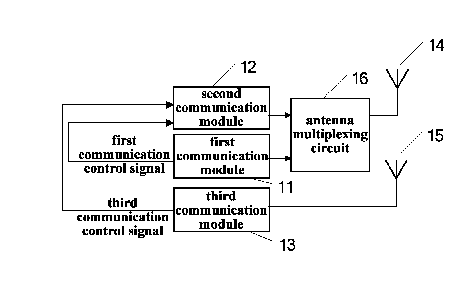
[0077]Exemplarily, as shown in FIG. 7, on the basis of the terminal shown in FIG. 1, the terminal further includes:

[0078]a third antenna 15, adapted to receive a third communication signal from a third correspondent node, or transmit a third communication signal to the third correspondent node; and

[0079]a third communication module 13, adapted to receive the third communication signal from the third antenna after the third antenna receives the third communication signal from the third correspondent node, or transmit the third communication signal to the third antenna before the third antenna transmits the third communication signal to the third correspondent node;

[0080]where the third communication module 13 is further adapted to, when transmitting the third communication signal to the third antenna, generate a third communication control signal for controlling the second communication module; and

[0081]the second communication module 12 is further adapted ...

third embodiment

[0109]The Third Embodiment

[0110]Exemplarily, as shown in FIG. 11, on the basis of the terminal shown in FIG. 1, the first antenna 14 and the second antenna 19 are two different antennas.

[0111]In a case that the first communication module transmits the first communication signal to the first antenna and at the same time the second communication signal is transmitted between the second communication module and the second antenna, signal interference occurs between the first communication module and the second communication module.

[0112]Specifically, the first communication module includes but is not limited to a GSM module, a CDMA module or a WCDMA module, and the second communication module is a GPS module, a BT module or a WLAN module.

[0113]In the embodiments of the invention, by controlling the first communication module and the second communication module to transmit at different times, the GSM module (alternatively, the CDMA module or the WCDMA module) and the GPS module (alterna...


PUM


Abstract

A communication terminal and a method for controlling data communication are provided by embodiments of the invention, relating to the field of communication technology. The communication terminal comprises: a first communication module adapted to, when transmitting a first communication signal to a first antenna, generate a first communication control signal for controlling a second communication module; and a second communication module adapted to receive the first communication control signal, and stop the transmission of a second communication signal between the second communication module and a second antenna in accordance with the first communication control signal. In the embodiments of the invention, respective signals of the first communication module and the second communication module are controlled to be transmitted in different times, thus signal interferences between the communication modules on the terminal are reduced.

Description

[0001]The present application claims the priority of Chinese Patent Application No. 201210121011.6, titled “COMMUNICATION TERMINAL AND METHOD FOR CONTROLLING DATA COMMUNICATION”, filed with the Chinese State Intellectual Property Office on Apr. 23, 2012, the entire disclosure of which are incorporated herein by reference.FIELD OF THE INVENTION[0002]The present invention relates to the field of communication technology, particularly to a communication terminal and a method for controlling data communication.BACKGROUND OF THE INVENTION[0003]Currently, mobile terminals support more and more functions, and user's demand on ultra-thin and minimal-sized communication terminals is increased. To reduce the size of the terminal, a mobile terminal is provided in the prior art, which supports three functions, i.e., GPS (Global Positioning System), BT (Bluetooth) and WLAN (Wireless Local Area Networks), by multiplexing a single antenna.[0004]However, when the existing mobile terminal implements...

Claims


Application Information

Patent Timeline
Patent Type & Authority Patents(United States)
IPC IPC(8): H04W72/04H04W72/12H04W88/06
CPCH04W72/0406H04W72/1215H04W88/06H04W72/20
Inventor SHAN, WENYINGZHANG, FULIANGZHANG, RONG
Owner LENOVO SOFTWARE
Learn More