Pulverizing apparatus and pulverizing method
a technology of pulverizing apparatus and pulverizing method, which is applied in grain treatment, grain milling, agriculture, etc., can solve the problems of part of the pulverized composition adhesion, and achieve the effect of reliably preventing the pulverized composition
- Summary
- Abstract
- Description
- Claims
- Application Information
AI Technical Summary
Benefits of technology
Problems solved by technology
Method used
Image
Examples
first embodiment
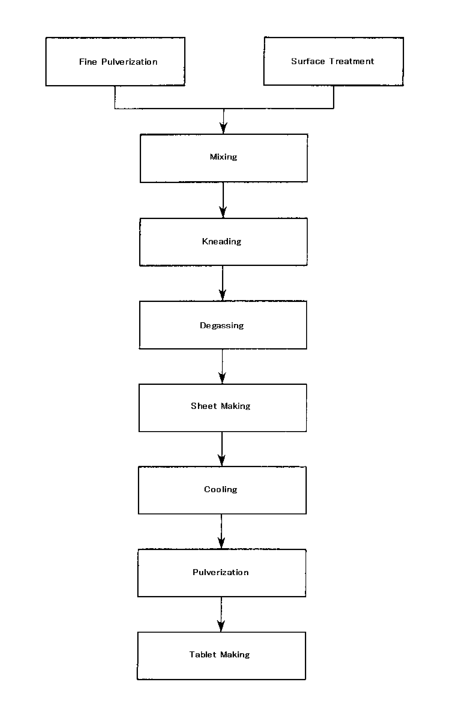
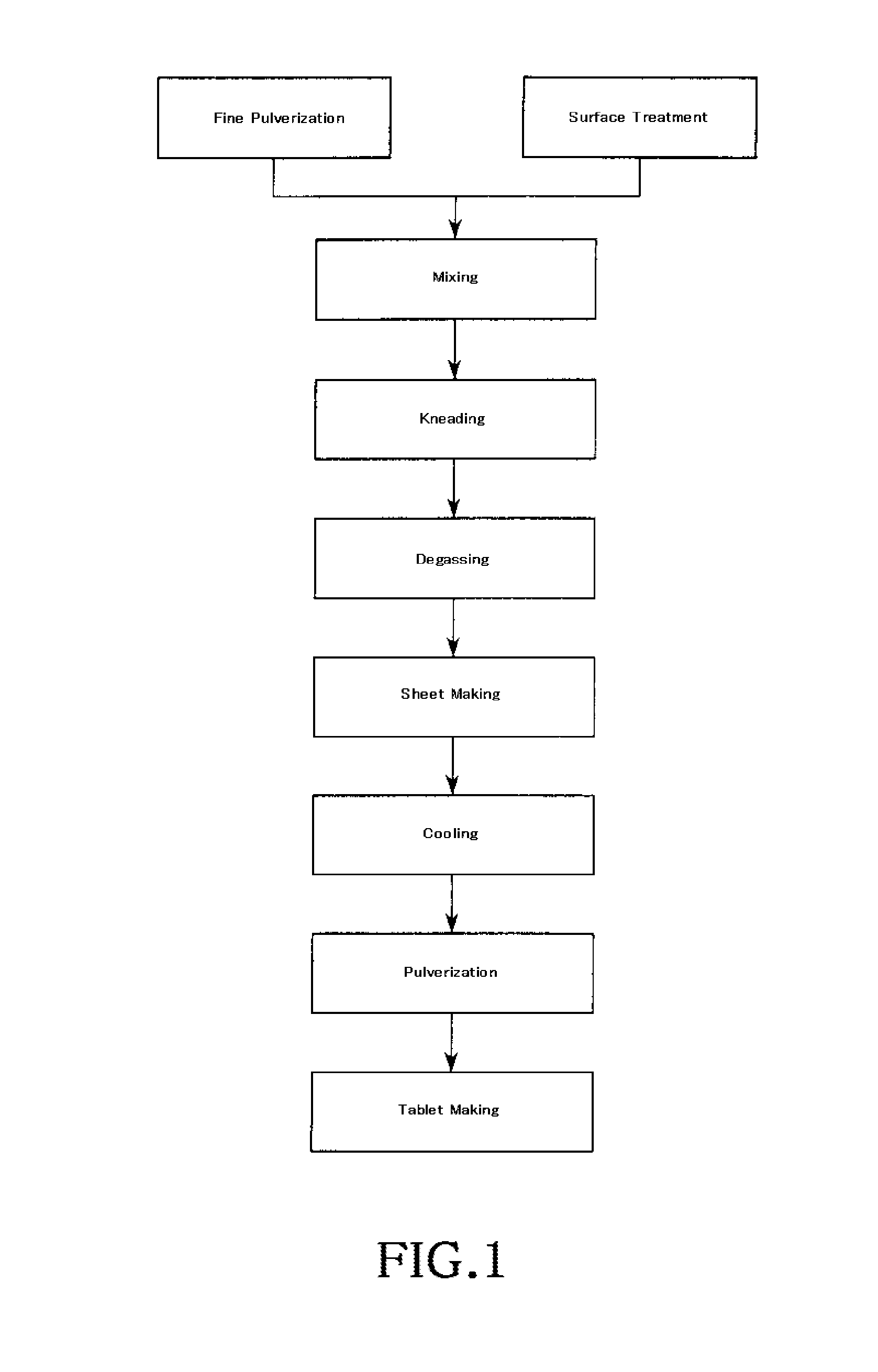
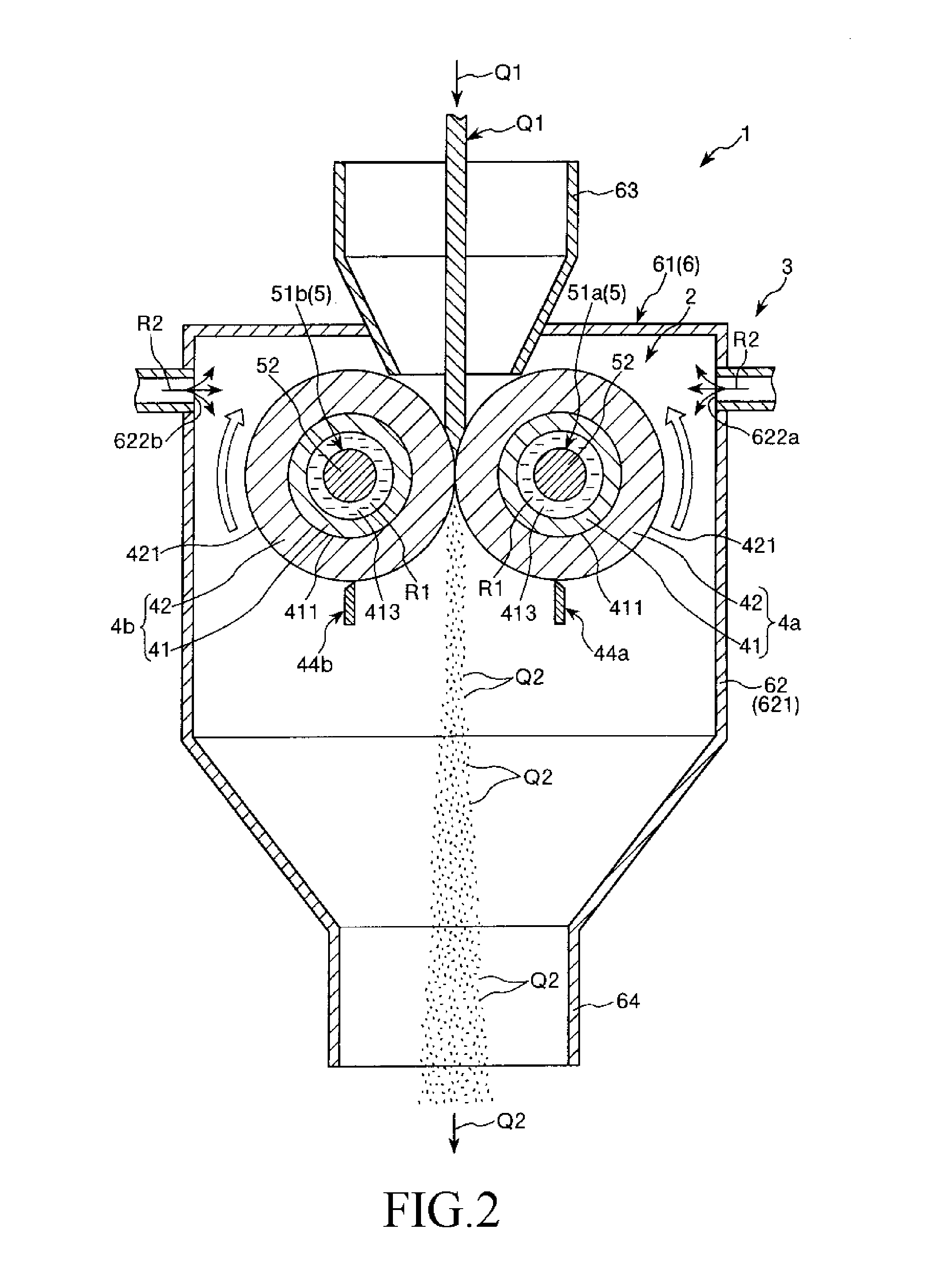
[0037]FIG. 1 is a process chart (view) showing a producing process of a resin composition. FIG. 2 is a cross section view showing a pulverizing apparatus according to the present invention. FIG. 3 is a partial cross section view showing a roller of the pulverizing apparatus shown in FIG. 2. FIG. 7 is a partial cross section view showing an IC package using a resin composition. In the following description, the upper side of FIGS. 2, 4 and 7 will be referred to as “upper” or “upper side”, the lower side will be referred to as “lower” or “downstream”. Further, the left side of FIG. 3 will be referred as “left” and the right side of FIG. 3 will be referred as “right”.
[0038]A pulverizing apparatus 1 of the present invention shown in FIG. 2 is a device used in a pulverizing process to produce a resin composition. This resin composition is finally molded into a molded body. Prior to describing the pulverizing apparatus 1, description will be first given to the overall producing process wh...
examples f
[0042 the filler material include a fused silica (having a crushed shape or a spherical shape), a crystalline silica and an alumina.
[0043]Examples of the curing accelerator include a phosphor compound and an amine compound. Examples of the coupling agent include a silane compound and so forth.
[0044]Specific one of the materials stated above may be excluded from the raw materials. Other materials than set forth above may be further included in the raw materials. Examples of the other materials include a coloring agent, a releasing agent, a stress-reducing agent and a flame retardant.
[0045]Examples of the flame retardant include a brominated epoxy resin, an antimony oxide-based flame retardant, a non-halo- and non-antimony-based flame retardant. Examples of the non-halo- and non-antimony-based flame retardant include an organic phosphor, a metal hydrate and a nitrogen-containing resin.
[0046](Fine Pulverization)
[0047]As shown in FIG. 1, specific materials among the raw materials are fi...
second embodiment
[0105]FIG. 4 is a cross section view showing the present invention.
[0106]Hereinbelow, description will be given to the second embodiment of the present invention with reference to FIG. 4. The second embodiment of the pulverizing apparatus and the pulverizing method will be described by placing emphasis on the points differing from the first embodiment of the pulverizing apparatus and the pulverizing method, with the same matters omitted from the description. The pulverizing apparatus and the pulverizing method according to the second embodiment are the same as the pulverizing apparatus and the pulverizing method according to the first embodiment, except the structure of the pulverizing mechanism.
[0107]The pulverizing mechanism 2A shown in FIG. 4 is configured to be capable of adjusting a center distance P between axes of the rollers 4a, 4b. Hereinbelow, descriptions will be given to the pulverizing mechanism 2A.
[0108]The roller 4a is configured to be capable of being moved in a dire...
PUM
| Property | Measurement | Unit |
|---|---|---|
| temperature | aaaaa | aaaaa |
| thickness | aaaaa | aaaaa |
| thickness | aaaaa | aaaaa |
Abstract
Description
Claims
Application Information
 - R&D
- Intellectual Property
- Life Sciences
- Materials
- Tech Scout
- Unparalleled Data Quality
- Higher Quality Content
- 60% Fewer Hallucinations
Browse by: Latest US Patents, China's latest patents, Technical Efficacy Thesaurus, Application Domain, Technology Topic, Popular Technical Reports.
© 2025 PatSnap. All rights reserved.Legal|Privacy policy|Modern Slavery Act Transparency Statement|Sitemap|About US| Contact US: help@patsnap.com


