
Modular lamp

a module lamp and lamp body technology, applied in the field of modular lamps, can solve the problems of major barriers to breaking free from poverty, lamps are dangerous and sometimes deadly to their users, and half a billion people in africa lack adequate access to artificial light and energy, and achieve the effect of convenient portability and rechargeability

Inactive Publication Date: 2016-08-09
KARIBU SOLAR POWER
View PDF18 Cites 2 Cited by
  • Summary
  • Abstract
  • Description
  • Claims
  • Application Information

AI Technical Summary

Benefits of technology

The present invention is a modular lamp that has different modules for different functions and can be easily recharged and adjusted for different uses. The first module contains a rechargeable power source and a light source, while the second module contains a solar panel. The modular lamp also has a diffuser or a third module for dispersing light. The solar panel can recharge the rechargeable power source when placed in an environment with sufficient solar intensity, and the second module can be detached from the first module and recharged for use in another modular lamp. The modular nature of the lamp allows for easy detachment of the third module, making it compact and easy to carry. The modular lamp can be used as a table lamp, a flash light, or a room light, and it is lightweight and portable.

Problems solved by technology

Over half a billion people in Africa lack adequate access to artificial light and energy.
This Is a major barrier from breaking free from poverty.
Such lamps are dangerous and sometimes deadly to their users; they are also hazardous to the environment.
Their toxic fumes are a leading cause of death for women and children.
Although partly successful, these efforts have been unable to scale to the point of making a sizeable impact.
Current solar solutions are often too expensive and unreliable.
Frequent moving of the solar lamp from Inside the house to outside is impractical and time consuming.

Method used


Image

  • Modular lamp
  • Modular lamp
  • Modular lamp

Examples


Embodiment Construction

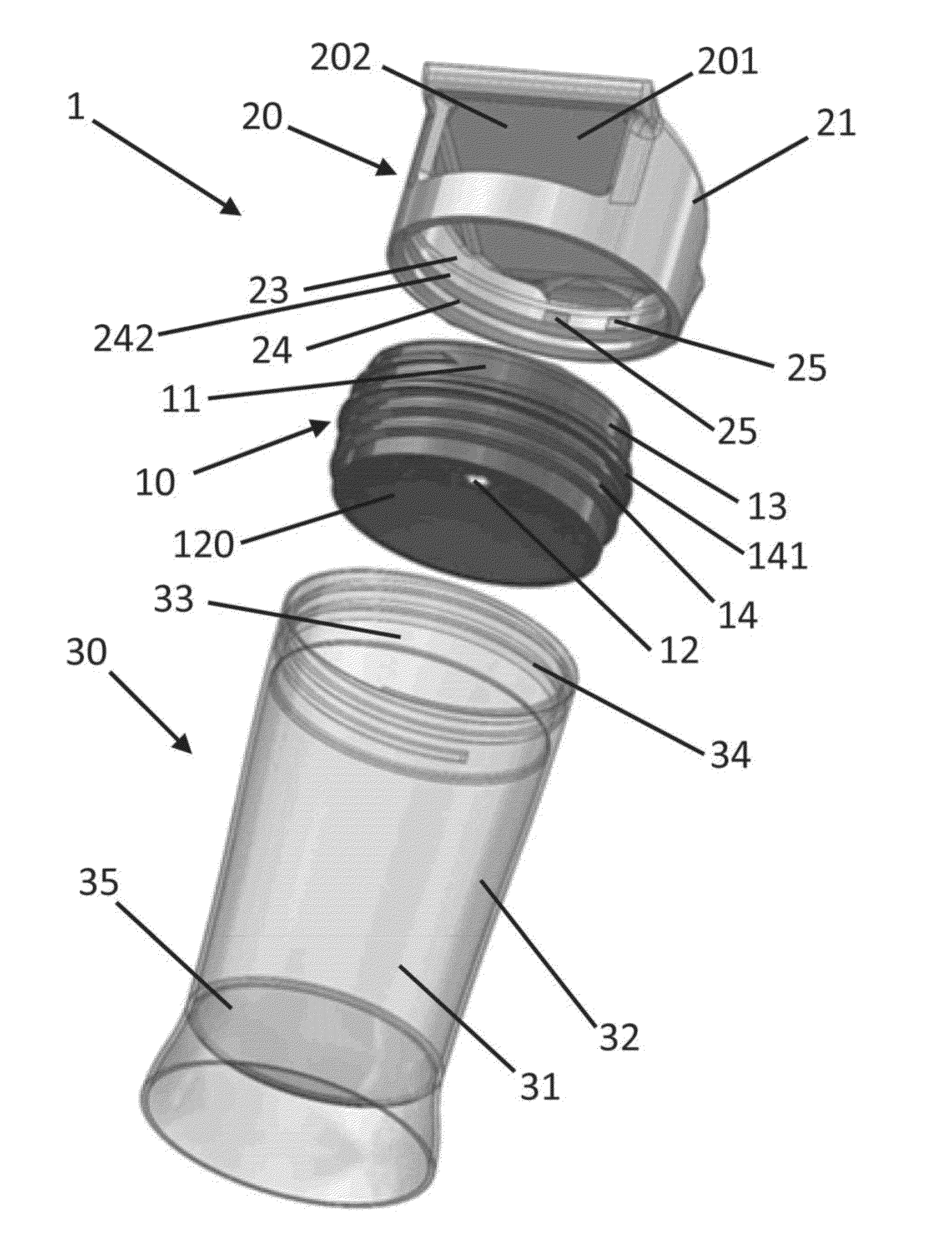
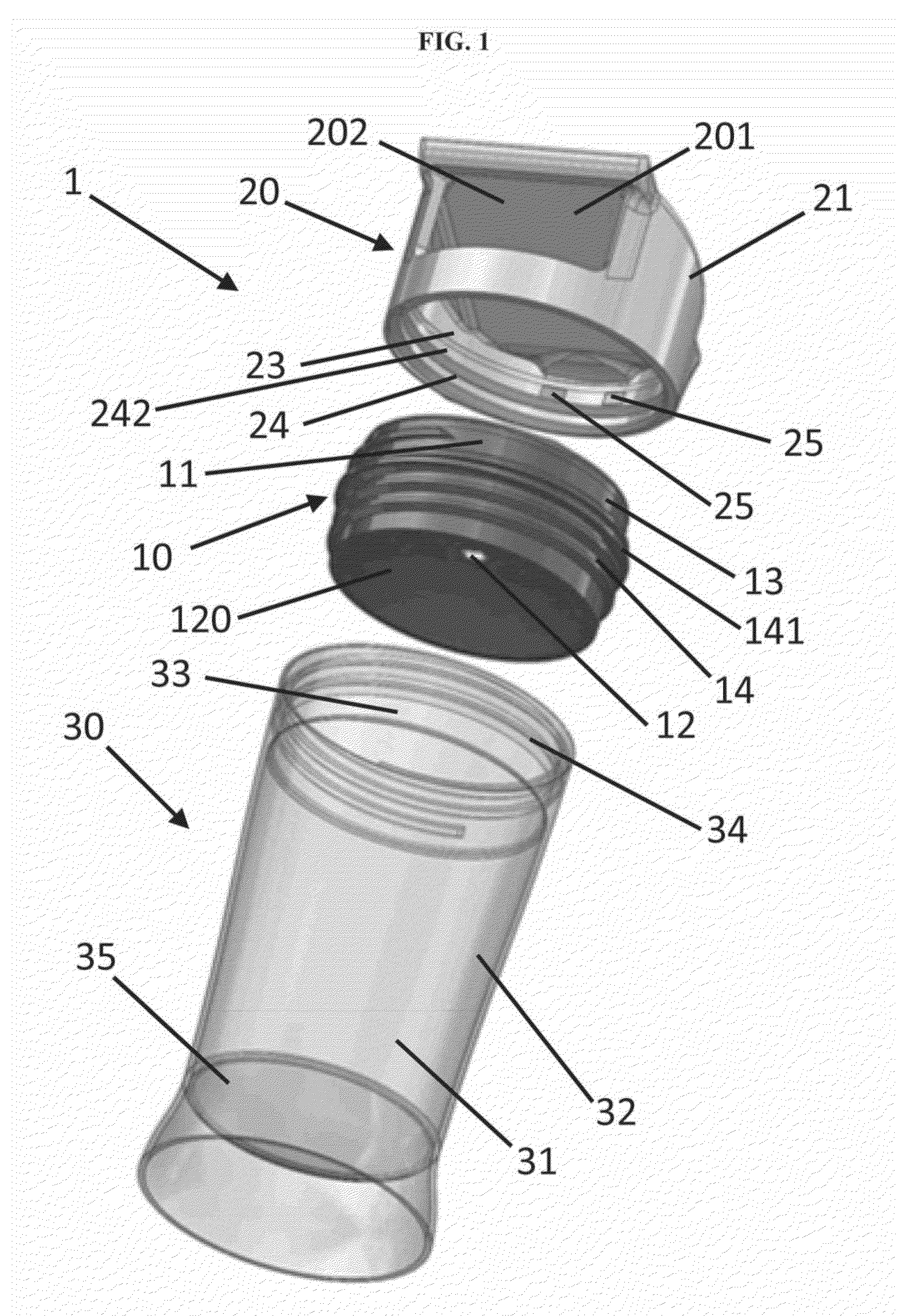
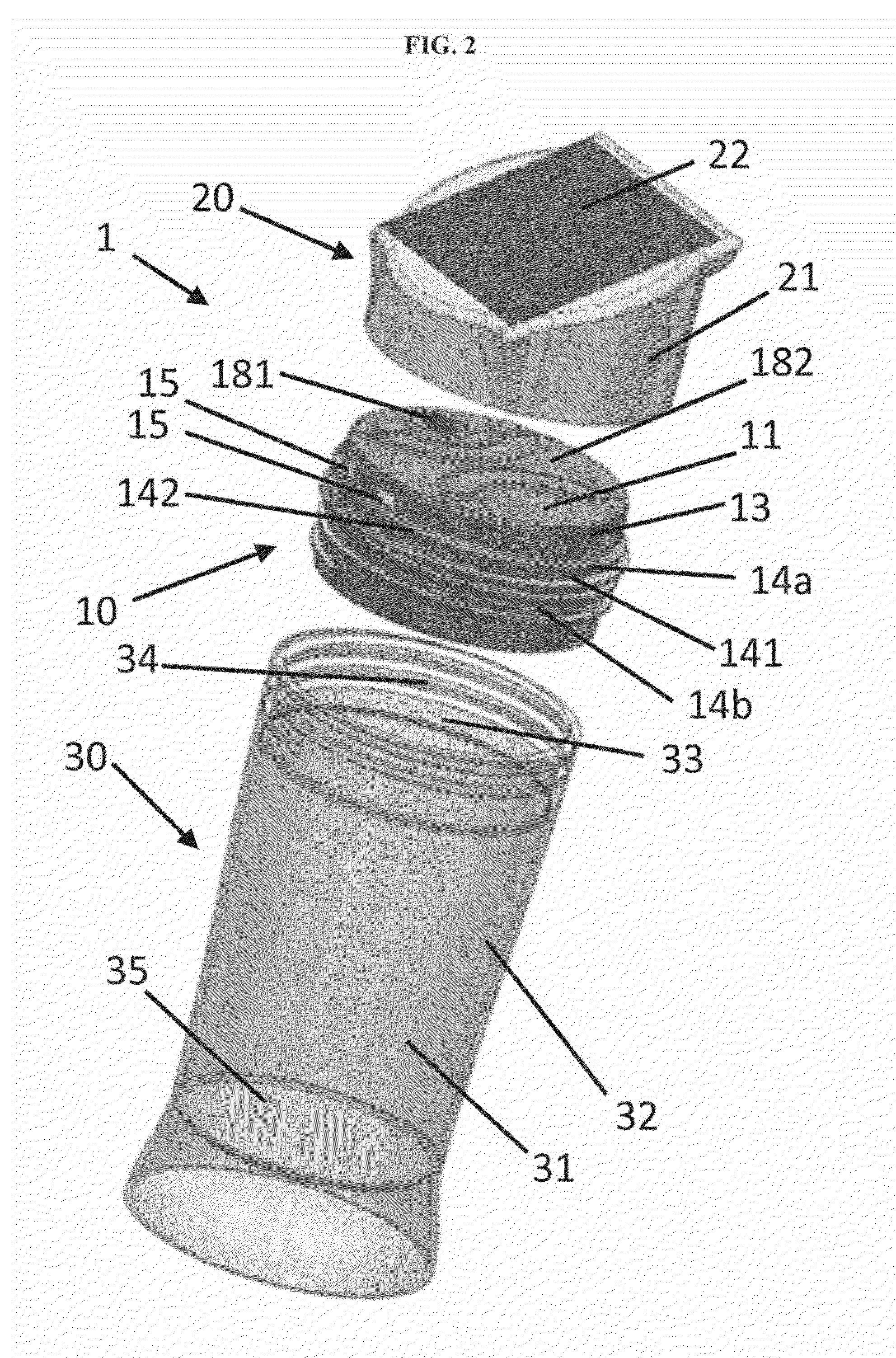
[0036]There is described a modular lamp, such, as modular solar lamp 1 as shown in FIGS. 1 to 5B and 7 to 8B. The modular solar lamp 1 may comprise a first module 10, such as battery / light module, a second module 20, such as solar module and a third module 30, such as diffuser module.

[0037]The battery / light module 10 may comprise a body 11 housing electrical components, including a rechargeable power source 16, used to power a light source 12 which may be located on a surface, such as surface 120 of the body 11. The surface 120 may be of reflective nature far reflecting and concentrating the light emitted by the light source 12. According to an embodiment, the external surface 13 of the body 11 has hastening means, such as threads 14. First electrical connecting means 15 may be exposed on an external surface of the body 11 and are in electrical connection with the electrical components housed in the body 11. According to an embodiment, the first electrical connecting means 15 are ex...


PUM


Abstract

A modular solar lamp is provided. The lamp has three detachable modules: a solar panel module, a battery / light module, and a diffuser module. The battery / light module has a battery connected to a light. Electrical connectors are located on a surface of the body and are electrically connected with the battery. The solar module has a solar panel exposed on its top surface for converting solar energy into electrical energy. Electrical connectors are located on a surface of the module and are electrically connected to the solar panel. The electrical connection is established between the solar panel and the battery module when the two modules are fully secured to each other thus establishing an electrical connection between the solar panel and the battery through the connectors. Once the battery is charged, the solar panel module may be detached and used to charge the battery of another lamp.

Description

FIELD OF THE APPLICATION[0001]The present application relates to artificial lighting, and more particularly, to a modular lamp.BACKGROUND OF THE APPLICATION[0002]Over half a billion people in Africa lack adequate access to artificial light and energy. This Is a major barrier from breaking free from poverty. To obtain artificial light once darkness has fallen, kerosene lamps are typically used. Such lamps are dangerous and sometimes deadly to their users; they are also hazardous to the environment. Their toxic fumes are a leading cause of death for women and children. Furthermore, the use of kerosene emits over 100 million tons of greenhouse gases every year.[0003]Over the past few decades, there has been an increase in the prevalence of renewable energy solutions to those lacking adequate access to light and energy. Although partly successful, these efforts have been unable to scale to the point of making a sizeable impact. Current solar solutions are often too expensive and unrelia...

Claims


Application Information

Patent Timeline
Patent Type & Authority Patents(United States)
IPC IPC(8): F21L4/04F21V23/00F21L4/00F21V3/04F21L4/08F21S8/00F21S9/03F21W131/30
CPCF21L4/08F21V3/049F21V23/005F21L4/005F21S8/03F21S9/032F21W2131/30F21Y2101/00F21Y2115/10
Inventor CAMENZULI, BRIANCAMENZULI, ADAM MATTHEW
Owner KARIBU SOLAR POWER
Learn More