Light guide plate
a technology of light guide plate and guide plate, which is applied in the direction of instruments, non-linear optics, lighting and heating apparatus, etc., can solve the problems of significant cost increase, increased color unevenness of outgoing light, and uneven luminance in outgoing light, so as to reduce the unevenness of luminance and color, easy to manufacture, and high light use efficiency
- Summary
- Abstract
- Description
- Claims
- Application Information
AI Technical Summary
Benefits of technology
Problems solved by technology
Method used
Image
Examples
example 1
[0232]In Example 1, the particle size distribution of scattering particles to be kneaded and dispersed in the light guide plate 30 shown in FIG. 3 was variously changed and the normalized intensity distributions (luminance distributions), the chromaticity distributions and the color differences of outgoing light were determined by computer simulation.
[0233]In Example 1, two particle groups each having a single particle size were mixed and used as scattering particles.
[0234]In the simulation, the material of the transparent resin of the light guide plate and the material of the scattering particles were modeled as PMMA and silicone particles, respectively. This will also apply to all the examples given below.
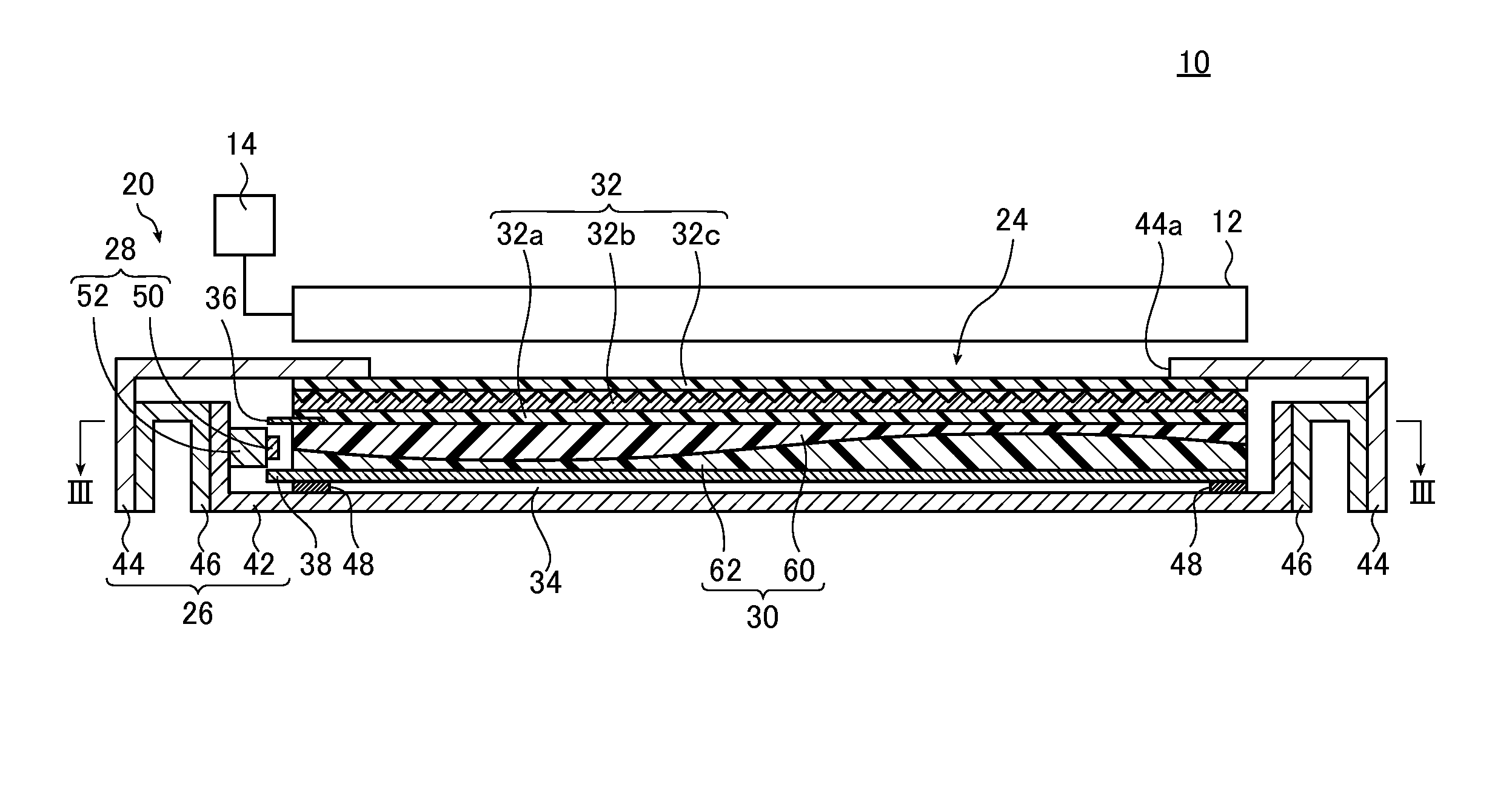
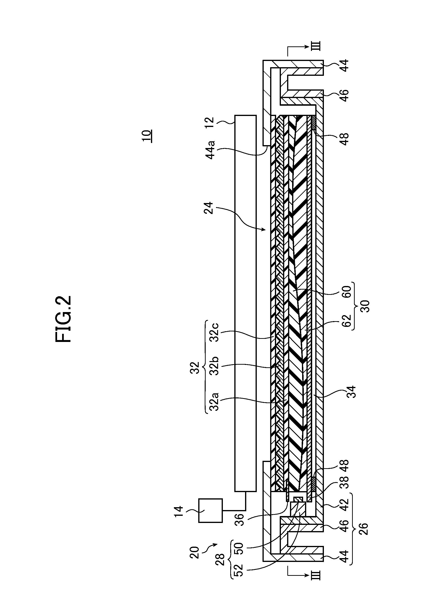
[0235]In Example 1-1, the light guide plate 30 corresponding to a 60-inch screen size was used. More specifically, the length L1g from the first light incidence surface 30c to the opposite lateral surface 30d (length of the light guide plate) was set to 780 mm.
[0236]The thickness...
example 2
[0273]Next, two monodisperse particle groups were mixed and used as scattering particles to determine the intensity distributions of outgoing light, the chromaticity distributions and the color differences.
[0274]The monodisperse particle groups for use in the examples are first described.
[0275]Four types of commercially available silicone particles (TOSPEARL 1100, TOSPEARL 120A, TOSPEARL 130A, and TOSPEARL 145T manufactured by Momentive Performance Materials Inc.) were used as models of monodisperse particle groups. The modeled particle groups are denoted by T1, T2, T3 and T4, respectively.
[0276]The particle size distributions of the particle groups T1, T2, T3 and T4 are shown in FIGS. 16A to 16D, respectively.
[0277]In FIGS. 16A to 16D, the vertical axis indicates the volume fraction (%) and the horizontal axis indicates the particle size (μm).
[0278]T1 has an average particle size of 10.0 μm, T2 an average particle size of 2.0 μm, T3 an average particle size of 3.0 μm, and T4 an ave...
example 3
[0292]In Example 3, the particle groups T1 and T3 were mixed and used as scattering particles.
[0293]In Example 3-1, Example 2-1 was repeated except that the particle groups T3 and T1 were mixed at a ratio of 35:65 (a=0.35) for scattering particles, thereby determining the intensity distributions of blue light, green light and red light, and the distributions of the chromaticities x and y, and the color differences Δx and Δy.
[0294]The results are shown in FIGS. 21A to 21C.
[0295]The color differences Δx and Δy were 0.0048 and 0.0053, respectively.
[0296]In Example 3-2, Example 3-1 was repeated except that the particle groups T3 and T1 were mixed at a ratio of 36.5:63.5 (a=0.365) for scattering particles, thereby determining the intensity distributions of blue light, green light and red light, and the distributions of the chromaticities x and y, and the color differences Δx and Δy.
[0297]The results are shown in FIGS. 22A to 22C.
[0298]The color differences Δx and Δy were 0.0011 and 0.000...
PUM
| Property | Measurement | Unit |
|---|---|---|
| particle size distribution | aaaaa | aaaaa |
| particle size | aaaaa | aaaaa |
| particle size distribution | aaaaa | aaaaa |
Abstract
Description
Claims
Application Information
 - R&D
- Intellectual Property
- Life Sciences
- Materials
- Tech Scout
- Unparalleled Data Quality
- Higher Quality Content
- 60% Fewer Hallucinations
Browse by: Latest US Patents, China's latest patents, Technical Efficacy Thesaurus, Application Domain, Technology Topic, Popular Technical Reports.
© 2025 PatSnap. All rights reserved.Legal|Privacy policy|Modern Slavery Act Transparency Statement|Sitemap|About US| Contact US: help@patsnap.com


