Eureka AIR delivers breakthrough ideas for toughest innovation challenges, trusted by R&D personnel around the world.

System and method for dynamic DCVS adjustment and workload scheduling in a system on a chip

a technology of dynamic dcvs and workload scheduling, which is applied in the field of system and method for dynamic dcvs adjustment and workload scheduling in a system on a chip, can solve the problems of insufficient space for engineers and designers, inability to run processing components in a pcd at their maximum rated power frequency without producing detrimental levels of thermal energy, and inability to optimize power consumption. , to achieve the effect of optimizing power savings, optimizing power consumption, and maximizing

Active Publication Date: 2016-08-09
QUALCOMM INC
View PDF10 Cites 1 Cited by
  • Summary
  • Abstract
  • Description
  • Claims
  • Application Information

AI Technical Summary

Benefits of technology

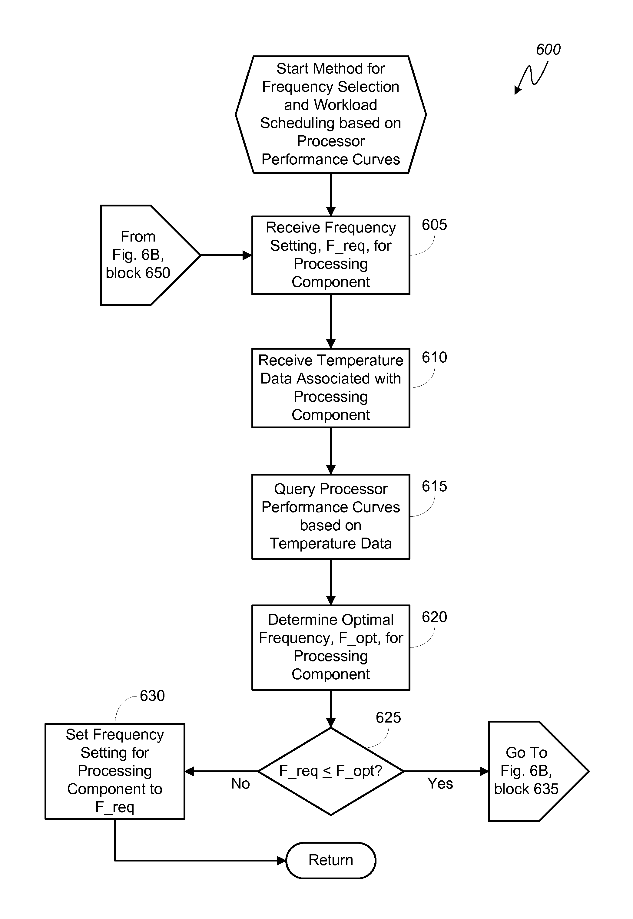
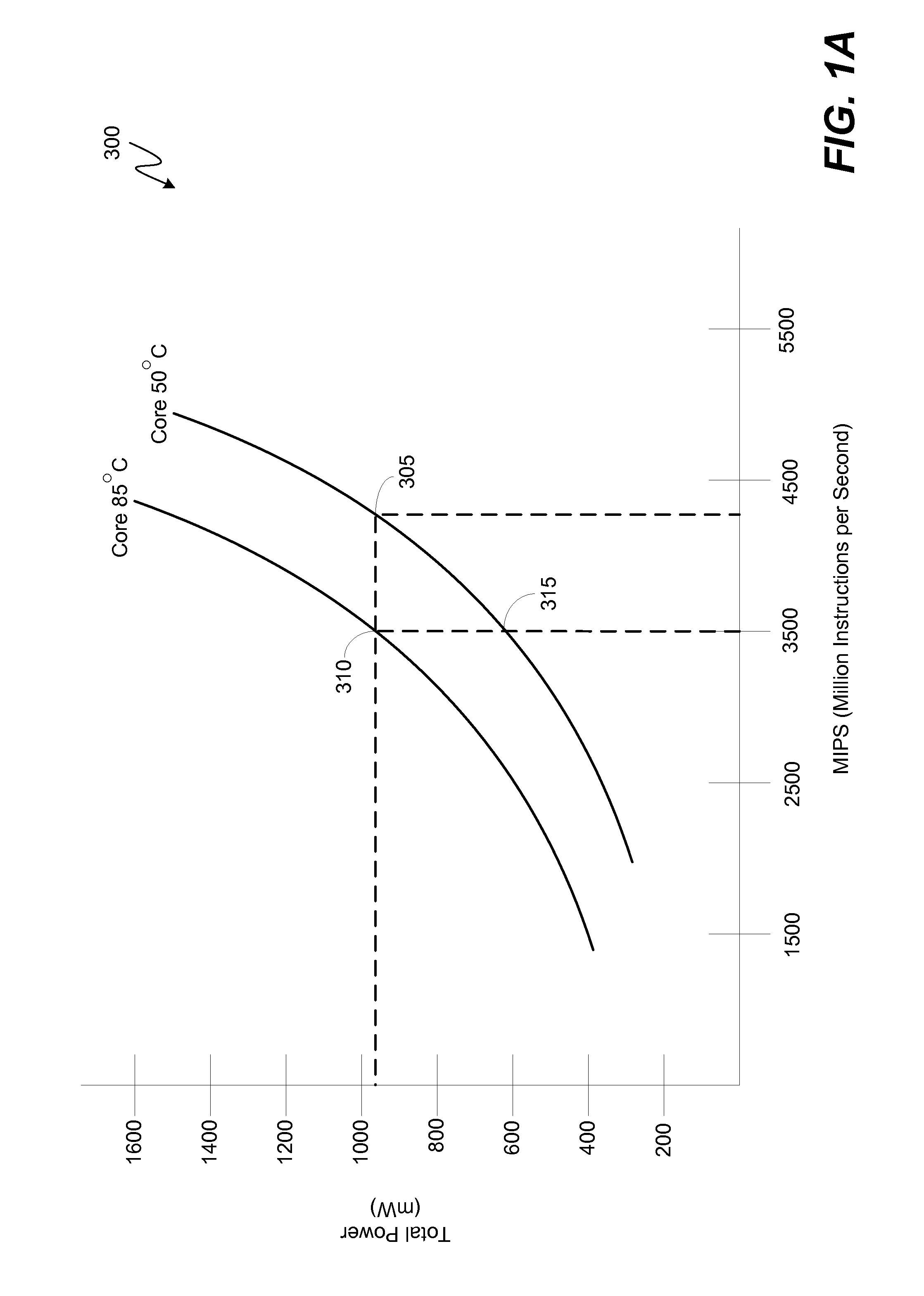
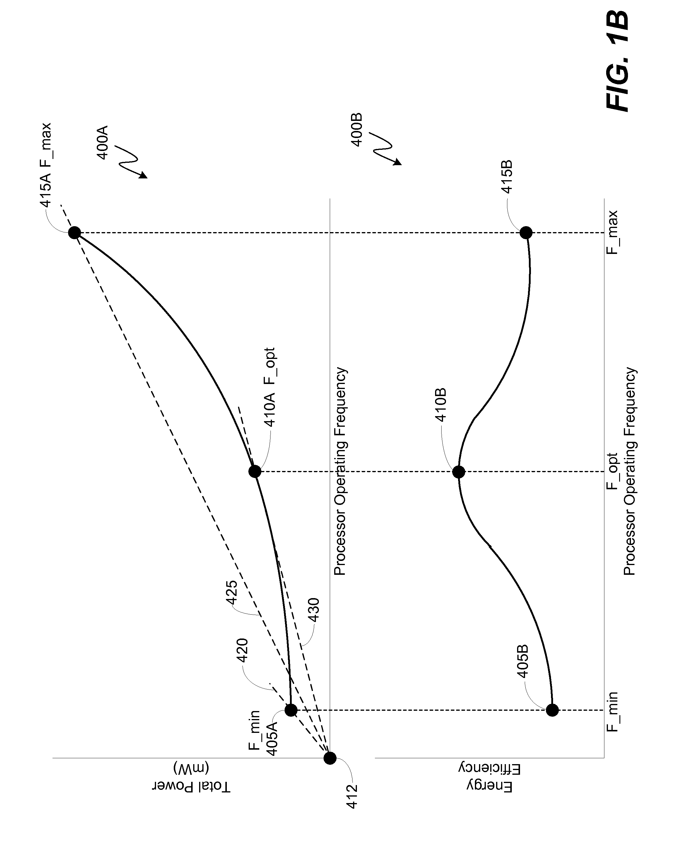
[0008]One such method involves receiving a request to adjust an operating frequency setting of a processing component to a requested frequency (“F_req”). Upon recognizing that the operating frequency for the processing component will be adjusted, readings of one or more static and / or dynamic factors (e.g., current leakage, voltage levels, operating temperature, power supply voltage margin, etc.) associated with the operation of the processing component may be taken. Using the operating readings, performance curves associated with the processing component may be queried. The performance curves comprise a representation of the relationship between power consumption and operating frequency for the processing component when operating at a given operating temperature. The performance curves are used to determine the optimal operating frequency (“F_opt”) for the processing component. When the processing component is supplied power at the F_opt frequency, the ratio of power consumed per workload processed is optimized. The F_opt is compared to the F_req and, if F_req is greater than or equal to F_opt, the operating frequency setting of the processing component is set to F_req. If, however, the F_req is less than F_opt, the operating frequency setting of the processing component is set to F_opt. Advantageously, when the operating frequency is set to F_opt in lieu of F_req, the processing time for a workload is shortened and the power consumed to process the workload is minimized per MIPS of workload.
[0010]Further, some embodiments of the systems and methods for dynamic DCVS adjustment envision that the power supplied to the processing component may be at the F_opt frequency and per a pulse width modulation (“PWM”) power management scheme. Advantageously, by supplying the power to the processing component at the F_opt frequency and per a PWM power management scheme, certain embodiments may optimize power consumption while the processing component is processing a block of code and optimize power savings after the block of code is processed as a power collapse period is maximized.

Problems solved by technology

Compact form factors, however, come with inherent design challenges.
For instance, in a PCD there typically is not enough space for engineers and designers to combat thermal degradation or failure of processing components through wide spacing arrangements or inclusion of passive cooling components.
Consequently, processing components in a PCD often cannot be run at their maximum rated power frequencies without producing detrimental levels of thermal energy.
Due to the limited form factors, however, simply including large power sources is usually not a solution for meeting a user's power supply expectations.
In a PCD that has heterogeneous processing components, the ramifications of balancing those tradeoffs can be difficult to manage because the various processing components within the PCD are not created equal.
For instance, the power frequency supplied to a processing component per a thermal mitigation technique or a power conservation scheme may not represent the most efficient point on the processor's performance curve.

Method used


Image

  • System and method for dynamic DCVS adjustment and workload scheduling in a system on a chip
  • System and method for dynamic DCVS adjustment and workload scheduling in a system on a chip
  • System and method for dynamic DCVS adjustment and workload scheduling in a system on a chip

Examples


Embodiment Construction

[0025]The word “exemplary” is used herein to mean “serving as an example, instance, or illustration.” Any aspect described herein as “exemplary” is not necessarily to be construed as exclusive, preferred or advantageous over other aspects.

[0026]In this description, the term “application” may also include files having executable content, such as: object code, scripts, byte code, markup language files, and patches. In addition, an “application” referred to herein, may also include files that are not executable in nature, such as documents that may need to be opened or other data files that need to be accessed.

[0027]As used in this description, the terms “component,”“database,”“module,”“system,”“thermal energy generating component,”“processing component,”“processing engine” and the like are intended to refer to a computer-related entity, either hardware, firmware, a combination of hardware and software, software, or software in execution. For example, a component may be, but is not lim...


PUM


Abstract

Various embodiments of methods and systems for dynamically adjusting operating frequency settings of one or more processing components in a portable computing device (“PCD”) are disclosed. One such method involves receiving a request to adjust an operating frequency setting of a processing component to a required frequency (“F_req”) to process a workload. Factor readings associated with the operating capacity of the processing component may be taken. Based on the readings, performance curves associated with the processing component may be queried. The performance curves are used to determine the optimal operating frequency (“F_opt”) for the processing component. The F_opt is compared to the F_req and, if the F_req is less than F_opt, the operating frequency setting of the processing component is set to F_opt. Advantageously, as compared to F_req, at F_opt workload processing may be more efficient and a low power mode may be entered sooner.

Description

DESCRIPTION OF THE RELATED ART[0001]Portable computing devices (“PCDs”) are becoming necessities for people on personal and professional levels. These devices may include cellular telephones, portable digital assistants (“PDAs”), portable game consoles, palmtop computers, and other portable electronic devices.[0002]From the perspective of a user, a compact form factor is a desirable aspect in a PCD. Compact form factors, however, come with inherent design challenges. For instance, in a PCD there typically is not enough space for engineers and designers to combat thermal degradation or failure of processing components through wide spacing arrangements or inclusion of passive cooling components. Consequently, processing components in a PCD often cannot be run at their maximum rated power frequencies without producing detrimental levels of thermal energy. In a PCD, thermal energy generation must be managed through the application of various thermal management techniques that may includ...

Claims


Application Information

Patent Timeline
Patent Type & Authority Patents(United States)
IPC IPC(8): G06F1/32G06F9/445G06F1/20
CPCG06F1/324G06F9/44505G06F1/206G06F1/329Y02B60/1217Y02B60/144Y02B60/1275Y02D10/00
Inventor PARK, HEE-JUNLEE, SEJOONGTHOMSON, STEVEN
Owner QUALCOMM INC
Why Eureka
Eureka Blog
Learn More