Ring cutting device and method

a cutting device and cutting ring technology, applied in the field of cutting devices and saws, can solve problems such as circumferential structural interferen

Active Publication Date: 2016-08-16
MORTON STEVEN D
View PDF19 Cites 4 Cited by
  • Summary
  • Abstract
  • Description
  • Claims
  • Application Information

AI Technical Summary

Benefits of technology

[0012]The blade is typically removably affixable to the drive shaft assembly effective to dispose the blade at an operable position with respect to the housing. In certain cases, an interface between the blade and drive shaft assembly is configured to cause a circumferential structural interference capable of transmitting torque to the blade. In a preferred embodiment, the torque is limited only by: resistance to blade spin; power source applied to said drive shaft assembly; or structural failure of a constituent component. One exemplary structural interference is formed between a spud of the drive shaft assembly and a cooperating rectangular socket formed in the blade, the spud having a rectangular cross-section and being received inside the socket upon assembly of the blade onto the drive shaft. Sometimes, one end of the drive shaft assembly is structured to couple with a motor to receive automated cutting power input. Other times, one end of the drive shaft assembly is structured to receive manual cutting power input from a user's non-stabilizing hand.
[0013]A workab

Problems solved by technology

In certain cases, an interface between the blade and drive shaft assembly is configured to

Method used


Image

  • Ring cutting device and method
  • Ring cutting device and method
  • Ring cutting device and method

Examples


Embodiment Construction

)

[0037]Reference will now be made to the drawings in which the various elements of the illustrated embodiments will be given numerical designations and in which the invention will be discussed so as to enable one skilled in the art to make and use the invention. It is to be understood that the following description is only exemplary of certain principles of the present invention, and should not be viewed as narrowing the claims which follow.

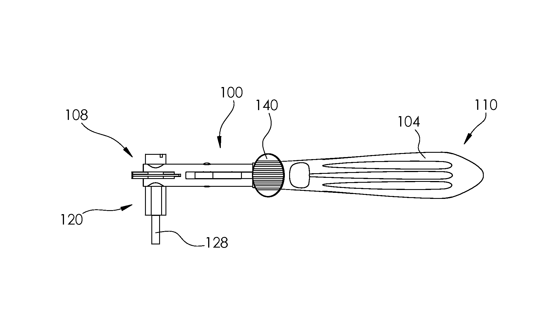
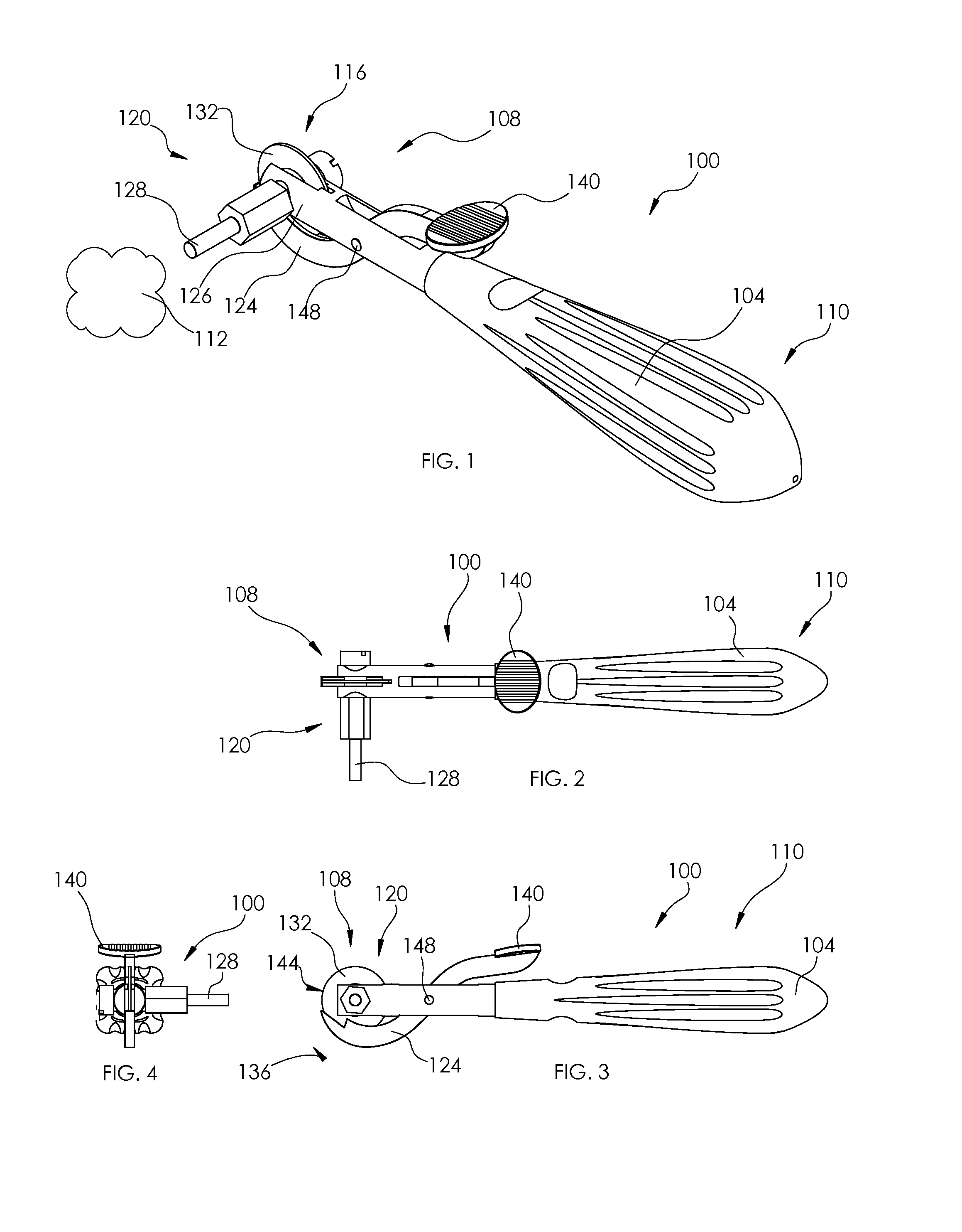
[0038]A first embodiment of a ring cutter, generally 100, structured according to certain principles of the invention is illustrated in FIGS. 1 through 4. Ring cutter 100 is particularly configured to facilitate cutting a jewelry ring from the finger of a human. An ambidextrous handle 104 extends proximally from a cutter assembly, generally 108. The proximal holding end 110 of handle 104 may be gripped in either the left hand, or the right hand, of a user. The hand that grasps the handle 104 is characterized as a stabilizing hand. In embodiment 1...


PUM

PropertyMeasurementUnit
Pressureaaaaaaaaaa
Poweraaaaaaaaaa
Electrical resistanceaaaaaaaaaa

Abstract

A specialized cutter adapted to remove a jewelry ring from a finger of a human hand. The cutter may include a diamond covered wheel having diamond grit sized between about 100-grit and about 170-grit. Preferably, the cutter can be assembled to permit either of a left-hand, or a right-hand mode of operation. Certain embodiments are structured to preclude relative motion between a cutting blade and the drive shaft on which it is mounted.

Description

BACKGROUND[0001]1. Field of the Invention[0002]This invention relates generally to saws and cutting devices. It is particularly directed to a cutter for removing an ornamental ring from a human finger.[0003]2. State of the Art[0004]Situations exist in which removing an ornamental jewelry ring from the finger on which it is worn requires cutting through at least one side, or wall, of the ring. For example, a ring that is too tight may cause a finger to swell to the point that the ring simply cannot be slid off in conventional fashion. Damage to a ring or finger (e.g. industrial accident), may also preclude conventional removal of a ring. In certain cases, a known ring cutter may be employed to cut through one side of the ring. Certain malleable rings (such as rings made from Copper, Gold, Silver, and other precious metals), may then be increased in diameter by prying the ring material apart in a circumferential direction. Sometimes, opposite sides of the ring must be cut through to e...

Claims


Application Information

Patent Timeline
IPC IPC(8): B23D45/16A44C9/00
CPCA44C9/0084B23D45/16B23D45/003
Inventor MORTON, STEVEN D.
Owner MORTON STEVEN D
Why Eureka
Try Eureka