
Speed limiting turbine with momentum activated bypass valve

a technology of speed limitation and bypass valve, which is applied in the direction of moving spraying apparatus, spraying apparatus, etc., can solve the problems of high speed, seize to plastic housing material, damage to sprinklers including water turbines,

Active Publication Date: 2016-08-16
KAH JR CARL L C
View PDF4 Cites 0 Cited by
  • Summary
  • Abstract
  • Description
  • Claims
  • Application Information

AI Technical Summary

Benefits of technology

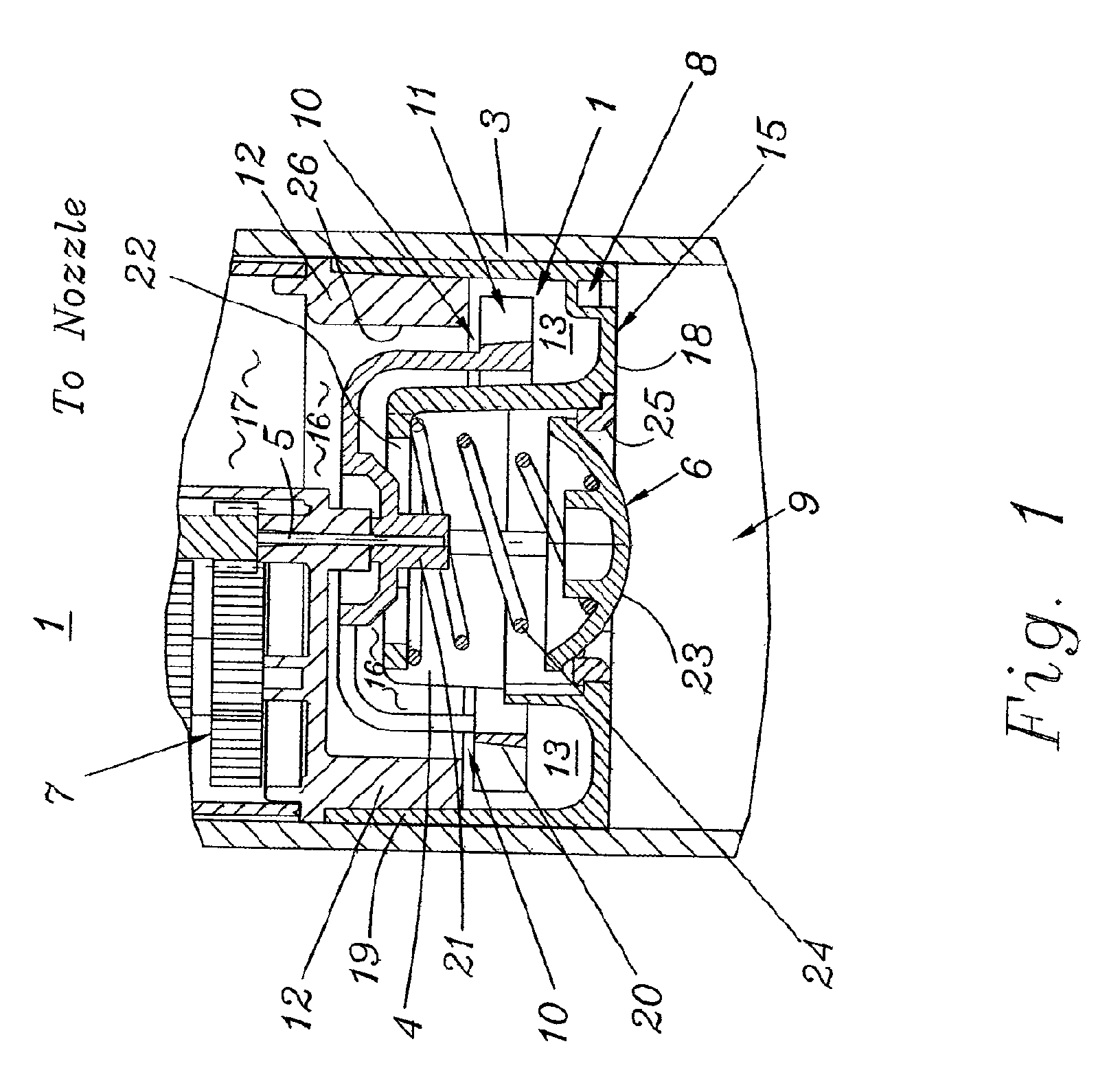
The present patent provides a turbine-driven sprinkler with a speed limiting mechanism that prevents damage to the turbine when using compressed air to prepare for winter. The mechanism also allows for satisfactory operation when the turbine is water-driven. Additionally, the patent aims to provide a reliable and cost-effective solution for the speed limiting mechanism for air.

Problems solved by technology

This can be very damaging to sprinklers including water turbines, which are normally water powered.
When air from blowing out the system drives the turbines, however, very high velocities result since air is an expandable, relatively light fluid, that expands across the turbine stator onto the turbine blades.
The high turbine shaft velocities resulting from such air driving the turbine can heat the shaft and cause it to seize to the plastic housing material.
This prevents the turbine from turning and renders it unusable in the future unless care is taken to limit the system air, blow-out time and pressures.
This has proven to be one of the major causes for premature failure of gear driven sprinklers in colder climates.
This design, however, cannot effectively limit rotational speed when the turbine is driven by a compressible fluid such as air, and still allow the turbine to run at a sufficiently high speed when it is driven by an incompressible fluid such as water because of the rapid expansion of the compressed air as it enters the turbine chamber.
Other turbine speed limiting mechanisms are known, but to applicant's knowledge, none are known that limit turbine over-speed by distinguishing the difference in the momentum of the turbine drive fluid when it contains air to divert a portion or all of the high velocity yet much lower momentum drive fluid around the turbine blades, thus limiting turbine available power and speed.

Method used


Image

  • Speed limiting turbine with momentum activated bypass valve
  • Speed limiting turbine with momentum activated bypass valve
  • Speed limiting turbine with momentum activated bypass valve

Examples


second embodiment

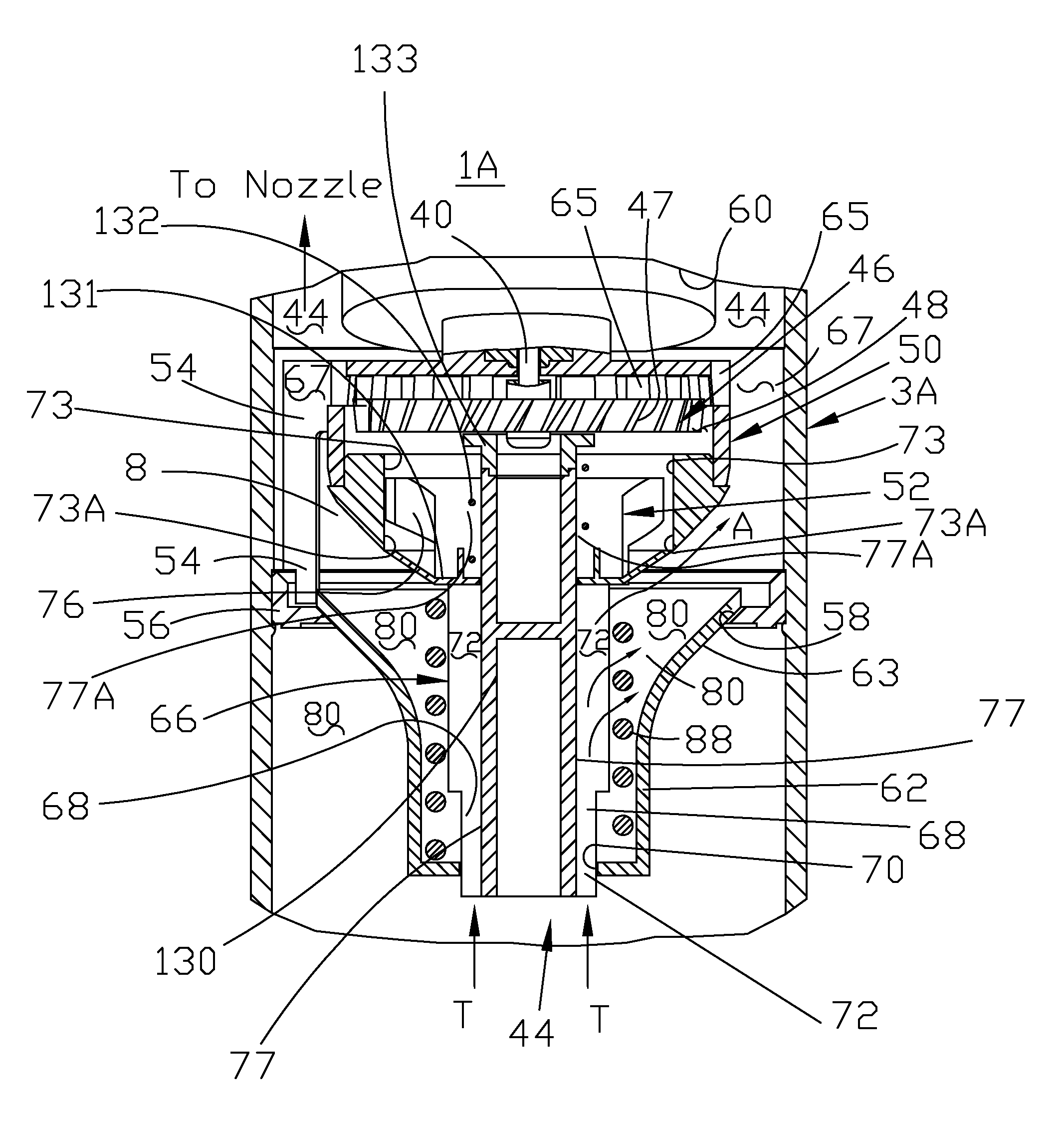
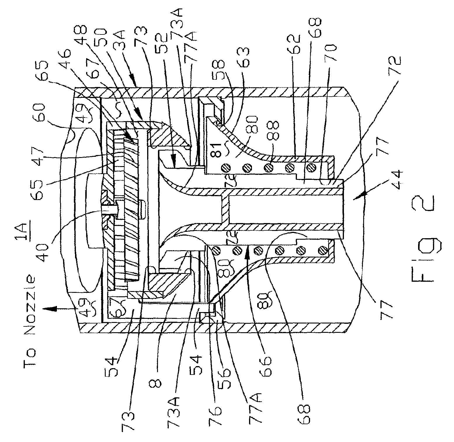
[0036]FIGS. 2-5 illustrate the present disclosure in which a different mechanism is employed for limiting turbine over-speed when it is run on compressed air during winterization.

[0037]Referring to FIGS. 2 and 3, modified turbine assembly 1A is mounted in a housing 3A, and, by way of an output shaft 40, drives a gearbox 60, which rotates or oscillates a sprinkler head (not shown). Water or compressed air entering turbine assembly 1A from below at 44 drives the turbine, and thereafter flows through outlet passages 67 and 49 to the sprinkler nozzle.

[0038]The turbine includes a rotor 46 located in a rotor chamber 48 formed by an internal housing 50 having spaced legs 54 around its outside circumference. A flow directing swirl member 52 includes a lower (upstream) body portion 66 having a plurality of circumferentially spaced longitudinal ribs 68. A by-pass flow valve 62 described below having a central opening 70 is positioned in radially spaced relationship around the upstream body po...

third embodiment

[0046]FIG. 6 shows a cross sectional elevation view of the drive turbine area 1B of a turbine driven sprinkler according to the present disclosure. In this embodiment, a second spring loaded bypass valve member 131 has been added which is preloaded by compression spring 133 that holds turbine bypass valve member 131 in its bypass position as shown in FIG. 6. The turbine flow velocity, as established through orifice areas 72 is directed upward against the bottom surface of the second spring loaded bypass valve member 131. If the flow through the orifice 72 is primarily air, the momentum imparted by this flow is insufficient to move the valve member 131.

[0047]Specifically, the momentum of air imparted against the spring loaded bypass valve member 131 is 1 / 20 that of water at the same pressure. Thus, where air is the primary medium flowing through the orifice 72, the valve member 131 will not be displaced upwardly against the biasing spring 133. In the bypass position illustrated in FI...


PUM


Abstract

A speed limiting mechanism for a turbine-driven fluid distribution apparatus usable with compressible fluid such as compressed air and incompressible fluid such as water. In one form, a flow restrictor is located in the turbine discharge flow path, with the turbine discharge port area selected in relation to the turbine inlet port area according to the desired turbine speed with compressed air. In another form, the incoming fluid flows downstream along the surface of the turbine stator, and is then diverted to enter the rotor chamber in the proper direction. A bleed area on the stator which permits a portion of a compressible fluid which has expanded as it flows along the stator surface to flow to bypass the turbine rotor. In another embodiment, a valve may be provided upstream from the turbine to selectively divert at least a portion of the pressurized fluid around the turbine when the pressurized fluid air or a combination of air and water.

Description

CROSS-REFERENCE TO RELATED APPLICATIONS[0001]The present application claims benefit of and priority to U.S. Provisional Patent Application Ser. No. 61 / 412,110 entitled SPEED LIMITING TURBINE WITH MOMENTUM ACTIVATED BYPASS VALVE filed Nov. 10, 2010, the entire content of which is hereby incorporated by reference herein.BACKGROUND[0002]1. Field of the Disclosure[0003]The present disclosure relates to a sprinkler with a water driven turbine that causes a sprinkler nozzle to rotate to provide coverage over a desired area. More specifically, the present disclosure relates to a sprinkler with a water driven turbine that includes at least one valve that selectively diverts fluid from the turbine to prevent over speeding when the fluid is air or a combination of air and water.[0004]2. Related Art[0005]Sprinkler systems in northern climates should be drained or blown-out with air to clear the water and to prevent freezing damage. In many cases the simplest installation provides only for allo...

Claims


Application Information

Patent Timeline
Patent Type & Authority Patents(United States)
IPC IPC(8): B05B3/04
CPCB05B3/045B05B3/0418B05B3/0463
Inventor KAH, JR., CARL L. C.
Owner KAH JR CARL L C
Learn More