Image integration unit and image integration method

a technology of image integration and image, applied in the field of image integration unit and image integration method, can solve the problems that the technology disclosed in patent document 1 cannot be applied to a camera installed on a vehicle, and it is difficult to obtain three-dimensional information of a moving body, etc., and achieve the effect of accurate integration and high precision

Inactive Publication Date: 2016-08-16
KONICA MINOLTA INC
View PDF15 Cites 2 Cited by
  • Summary
  • Abstract
  • Description
  • Claims
  • Application Information

AI Technical Summary

Benefits of technology

[0008]With the foregoing in view, it is an object of the present invention to provide an image integration unit and image integration method, which can integrate time-series images imaged while moving, at high precision.
[0009]The image integration unit of the present invention extracts a stationary body area from each time-series image, and integrates the time-series images by matching the corresponding stationary body areas between the time-series images. Thereby the time-series images, including the images of moving bodies and stationary bodies, can be accurately integrated.

Problems solved by technology

This means that the technology disclosed in Patent Document 1 cannot be applied to a camera installed on a vehicle, which is a moving body.
The technology disclosed in Patent Document 2 is not a technology assuming the use for analyzing the situations of an accident, and can obtain only three-dimensional information of a stationary body.
Therefore in the case of the technology disclosed in Patent Document 2, it is difficult to obtain three-dimensional information of a moving body, such as a vehicle and a pedestrian, even if three-dimensional information of such stationary bodies as a road surface, traffic lights and traffic signs, can be obtained.Patent Document 1: Japanese Patent Application Laid-Open No. 2004-102426Patent Document 2: Japanese Patent Application Laid-Open No.

Method used


Image

  • Image integration unit and image integration method
  • Image integration unit and image integration method
  • Image integration unit and image integration method

Examples


Embodiment Construction

[0018]An embodiment of the present invention will now be described with reference to the drawings. In each drawing, composing elements denoted with a same reference numerals are a same composing element, and redundant description thereof is omitted.

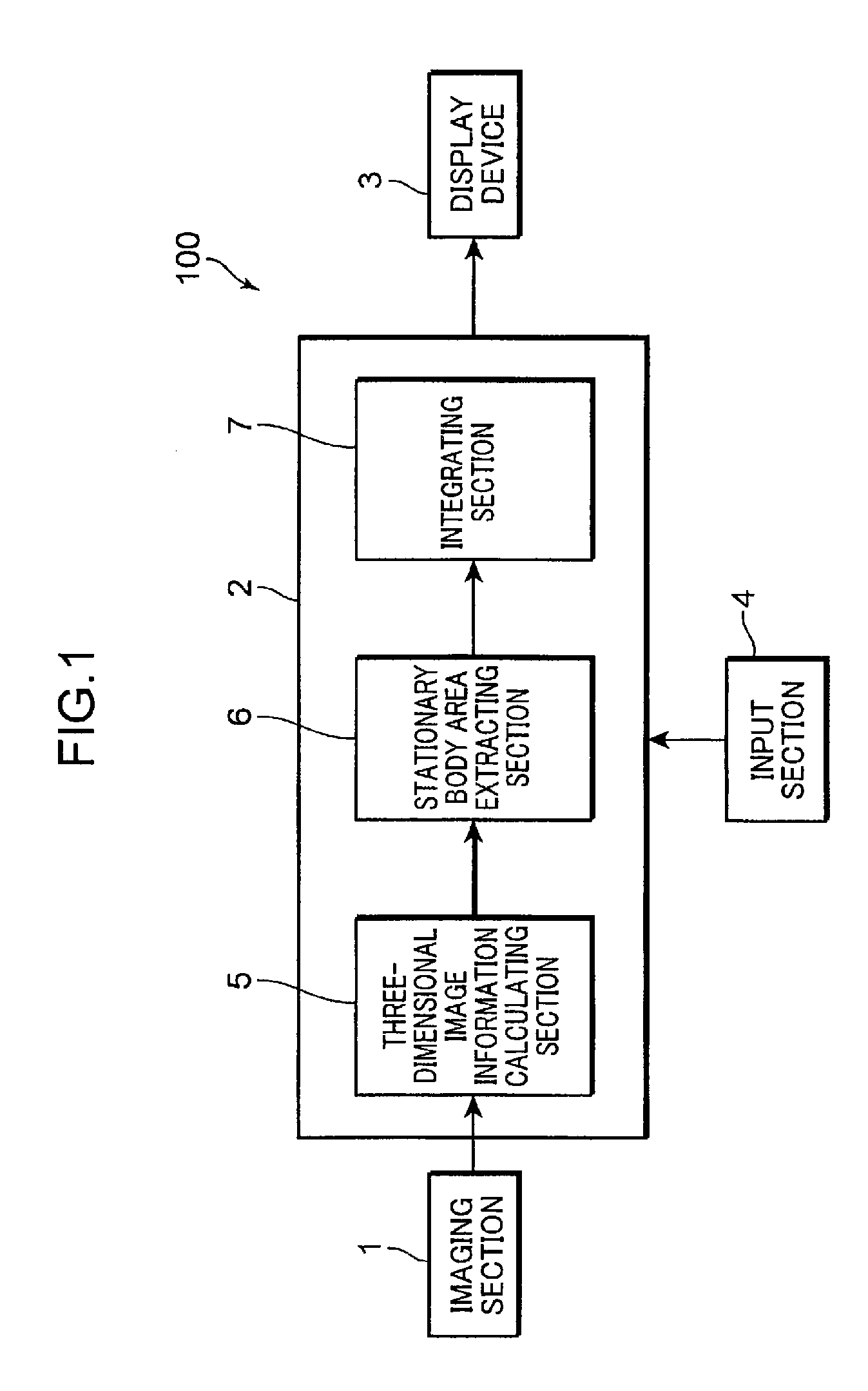
[0019]First a configuration of an image integration unit according to an embodiment of the present invention will be described. FIG. 1 is a block diagram depicting the configuration of the image integration unit according to an embodiment of the present invention. As FIG. 1 shows, the image integration unit 100 is provided with an imaging section 1, a processing section 2, a display device 3, and an input section 4. The imaging section 1 is installed in such a moving body as a vehicle, and obtains time-series images. The imaging unit 1 is a camera having such a image sensor as a CCD (Charge-Coupled Device). The imaging section 1 is preferably a stereo camera constituted by two cameras, which are disposed at the left and right with an appr...


PUM


Abstract

An image integration unit includes: an imaging section which is installed in a moving body and which images a plurality of time-series images at different times; a three-dimensional image information calculating section which calculates three-dimensional image information in each of the time-series images based on the time-series images imaged by the imaging section; a stationary body area extracting section which extracts stationary body areas in each of the time-series images based on the three-dimensional image information; and an integrating section which calculates the corresponding stationary body areas between the time-series images from each of the stationary body areas extracted in each of the time-series images, and matches the corresponding stationary body areas to integrate the time-series images.

Description

[0001]This application is the National Stage Application of International Patent Application No. PCT / JP2009 / 056590, filed Mar. 31, 2009.TECHNICAL FIELD[0002]The present invention relates to an image integration unit and an image integration method for integrating time-series images.BACKGROUND ART[0003]Recently research on various systems for improving safety is ongoing in the automobile industry. In particular, a crisis avoidance system using an image sensor having an imaging apparatus has been developed. Specifically, a system which specifies an obstacle around a vehicle and which analyzes the movement of the obstacle based on images imaged by the imaging apparatus, whereby the vehicle avoids the obstacle, has been developed.[0004]A system which extracts various information that is useful for investigating a cause of an accident by analyzing images before and after the accident has also been developed for cases when a crisis could not be avoided and an accident occurred. For exampl...

Claims


Application Information

Patent Timeline
Patent Type & Authority Patents(United States)
IPC IPC(8): B60R1/00G06T7/20
CPCB60R1/00G06T7/2033B60R2300/107B60R2300/30G06T2207/20048G06T2207/10021G06T2207/30252G06T7/246
Inventor SUMITOMO, HIRONORI
Owner KONICA MINOLTA INC
Why Eureka
Try Eureka