
Numerical controller having function of re-machining thread cutting cycle

a technology of a controller and a cutting cycle, which is applied in the direction of electric programme control, program control, instruments, etc., can solve the problems of inability to determine the amount of phase deviation for carrying out one-edge cutting, inability to obtain the feed axis direction for starting the thread cutting, and inability to obtain the one-edge cutting

Active Publication Date: 2016-08-16
FANUC LTD
View PDF12 Cites 2 Cited by
  • Summary
  • Abstract
  • Description
  • Claims
  • Application Information

AI Technical Summary

Benefits of technology

[0028]Since the present invention is provided with the above structures, the present invention can provide the numerical controller having the function of carrying out re-machining of thread cutting cycle for machining a screw thread in line with the originally expected screw thread phase, on the basis of the re-machining using the one-edge cutting or the zigzag cutting.

Problems solved by technology

As a result, there is a problem that not only the advantage of the thread cutting based on the one-edge cutting cannot be obtained, but also a phase is deviated from an originally expected screw thread phase.
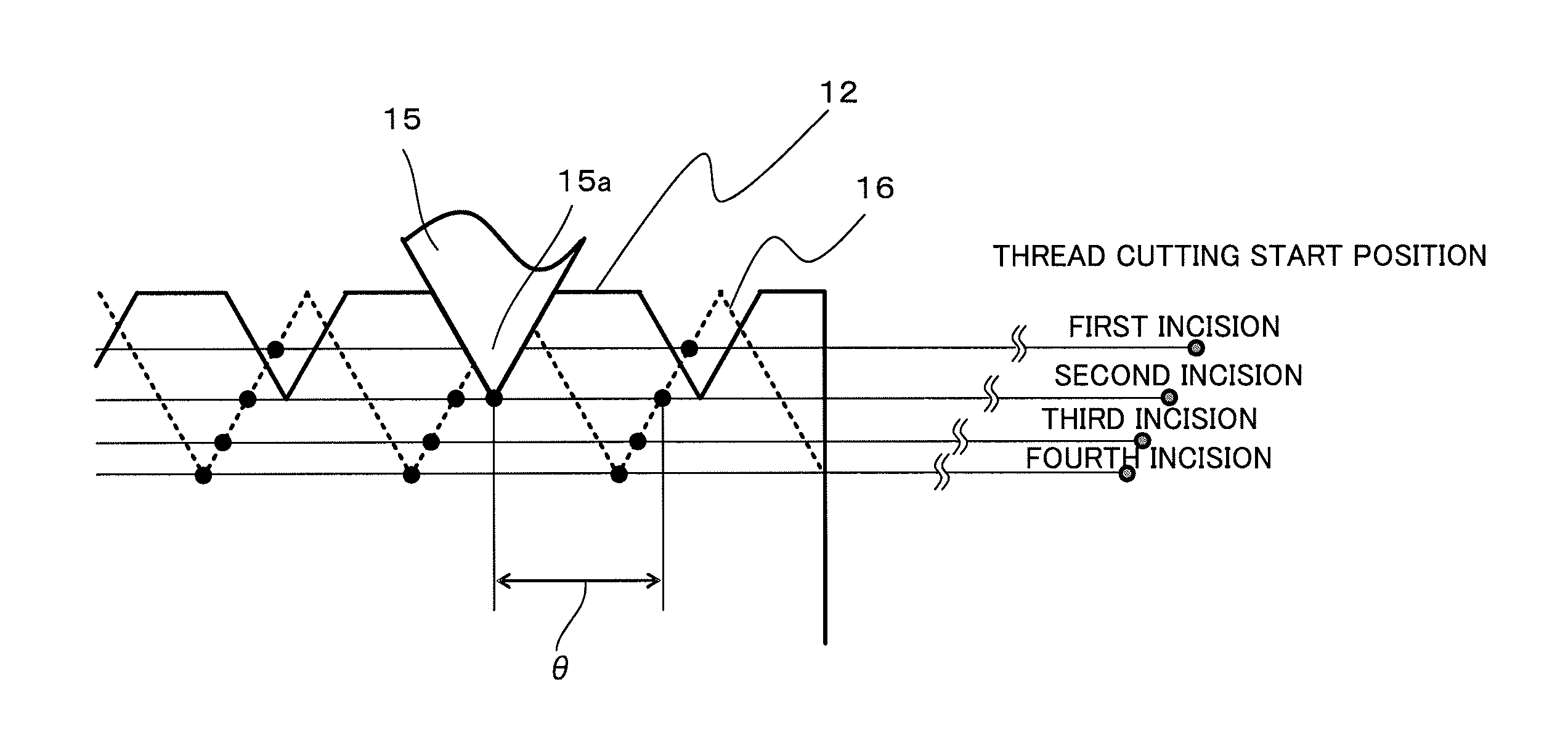
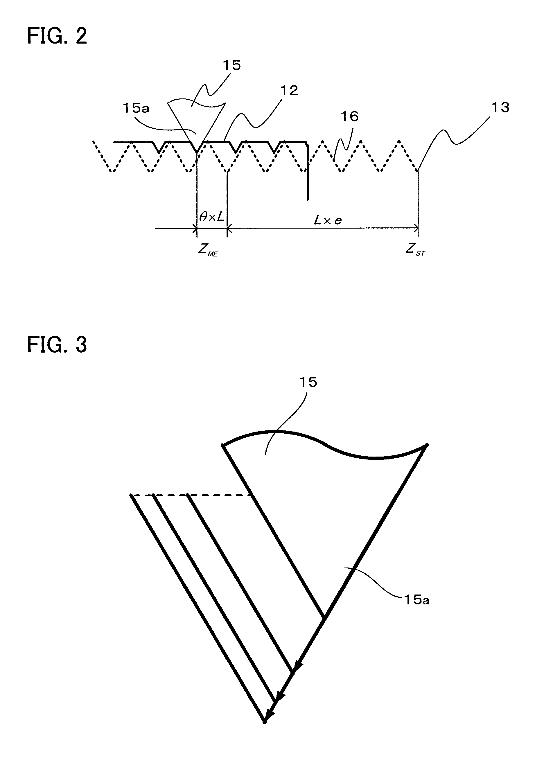
However, since the position ZST in the feed axis direction for starting the thread cutting varies on the basis of the number of incisions, the position ZST in the feed axis direction for starting the thread cutting cannot be obtained until how many incisions have been made until the measured thread groove is machined is known.
As a result, it is impossible to determine the amount θ of phase deviation for carrying out the one-edge cutting.
The conventional method of measuring the thread groove does not have any means for specifying the number of incisions, and cannot calculate the amount of phase deviation for carrying out the thread cutting using the one-edge cutting or the zigzag cutting.
Therefore, not only the advantage of the thread cutting using the one-edge cutting or the zigzag cutting cannot be obtained, but also there is a problem that the phase is deviated from the originally expected phase of the screw thread.

Method used


Image

  • Numerical controller having function of re-machining thread cutting cycle
  • Numerical controller having function of re-machining thread cutting cycle
  • Numerical controller having function of re-machining thread cutting cycle

Examples


Embodiment Construction

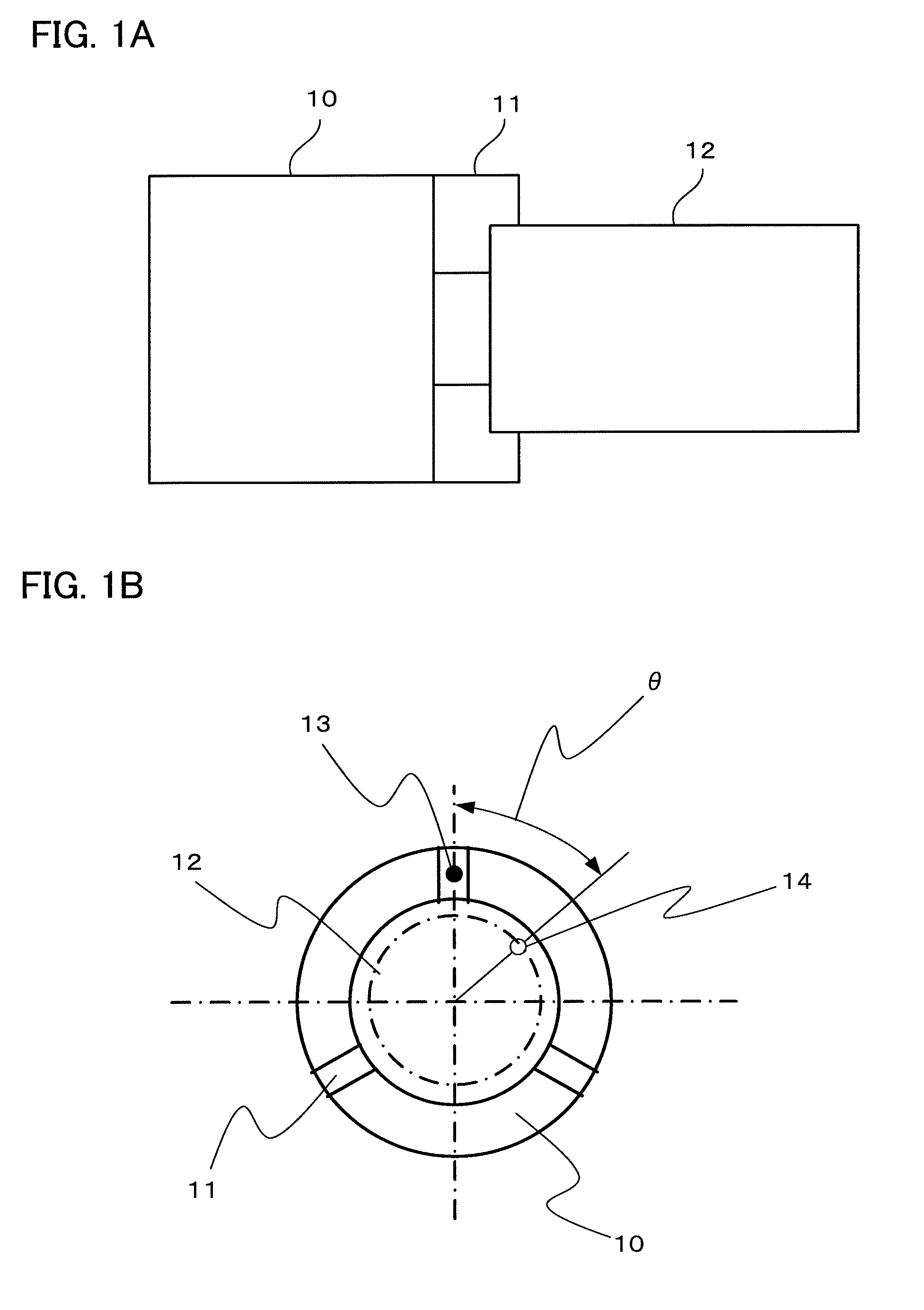
[0041]A numerical controller having a function of re-machining a thread cutting cycle is provided with a storage device (a memory), a CPU (an arithmetic processor), an interface which transmits and receives data to / from an input and output device including a keyboard and a display, and an interface which transmits and receives data to / from a drive circuit of a motor for each of axes driving each of axes of a machine tool. The motors drive axes, such as a spindle to which a chuck 10 for griping a workpiece is connected and a drive axis which moves a tool, and each of these motors is provided with a position detector which detects a rotational position of the motor. The positional information detected by the position detector is transmitted to the numerical controller. The storage device stores software executing the thread cutting cycle in the storage device. It is known that the structure mentioned above is provided in the numerical controller which controls the machine tool carryin...


PUM

PropertyMeasurementUnit
phaseaaaaaaaaaa
phase deviationaaaaaaaaaa
θaaaaaaaaaa

Abstract

A numerical controller controlling a machine tool calculates a number of incisions to a thread on the basis of an incision start position in a feed axis direction and an incision start position in a direction of an incision axis of a thread which are measured in a state in which a workpiece (a thread in the process of machining) is attached to a chuck of the machine tool, calculates an amount of phase deviation of a screw thread caused by reattachment of the workpiece on the basis of the calculated number of incisions, and re-machines the thread by positioning the workpiece and the tool while taking into consideration of the amount of phase deviation.

Description

RELATED APPLICATION DATA[0001]This application claims priority under 35 U.S.C. §119 and / or §365 to Japanese Application No. 2013-006360 filed Jan. 17, 2013, the entire contents is incorporated herein by reference.BACKGROUND OF THE INVENTION[0002]1. Field of the Invention[0003]The present invention relates to a numerical controller for controlling a machine tool carrying out thread cutting, and more particularly to a numerical controller having a function of re-machining a thread cutting cycle.[0004]2. Description of the Related Art[0005]In the following description, reattaching a thread which is once detached from a chuck of a machine tool to the chuck so as to machine the thread, in the case where a thread which is interrupted to be machined due to breakage of a tool is re-machined, or in the case where a finish machining of the thread is achieved by the other machine after the thread is roughly machined or intermediately machined, is referred to as “re-machining of thread”.[0006]F...

Claims


Application Information

Patent Timeline
Patent Type & Authority Patents(United States)
IPC IPC(8): G06F19/00B23B3/28B23B1/00G05B19/18H02P5/46
CPCG05B19/182G05B2219/45215G05B2219/50211G05B2219/50225
Inventor IRIE, KOUHEIOGAWA, SHUJI
Owner FANUC LTD
Learn More