Bearing seal for fan motor

a technology for bearing seals and fan motors, applied in the direction of liquid fuel engines, machines/engines, mechanical equipment, etc., can solve the problems of oil leakage out of the motor housing, difficulty in assembling etc., to reduce processing time, minimize oil leakage, and simplify the effect of assembly of upper and lower felt covers

Active Publication Date: 2016-08-16
NEW MOTECH
View PDF25 Cites 0 Cited by
  • Summary
  • Abstract
  • Description
  • Claims
  • Application Information

AI Technical Summary

Benefits of technology

[0010]It is another object of the present invention to provide a fan motor which simplifies assembly of upper and lower felt covers so as to reduce processing time required to manufacture a motor housing.
[0011]It is a further object of the present invention to provide a fan motor which includes an oil ring additionally mounted to minimize oil leakage.
[0016]Furthermore, an upper oil ring is mounted on the upper side of the upper felt cover to prevent oil leakage between the upper felt cover and the first bracket.
[0018]Moreover, a lower oil ring is mounted on the upper side of the lower felt cover to prevent oil leakage between the lower felt cover and the second bracket.
[0020]The fan motor according to the preferred embodiment of the present invention provides a structure that the upper and lower felt covers are easily joined to the first and second brackets so as to reduce processing time by simplifying assembling work of the motor housing.
[0021]Additionally, the fan motor according to the preferred embodiment of the present invention includes the oil ring additionally mounted on the upper and lower felt covers in order to minimize oil from leaking to the outside.

Problems solved by technology

However, such a motor structure has several disadvantages in that it is difficult to assemble upper and lower felt covers serving to seal a space to which oil is supplied to smoothly rotate a bearing and in that oil leaks out of the motor housing in a case of misassembly.

Method used


Image

  • Bearing seal for fan motor
  • Bearing seal for fan motor
  • Bearing seal for fan motor

Examples


Embodiment Construction

[0029]Reference will be now made in detail to the preferred embodiments of the present invention with reference to the attached drawings. In the drawings, the same components have the same reference numerals and the same names, and additional descriptions of the components will be omitted in the following.

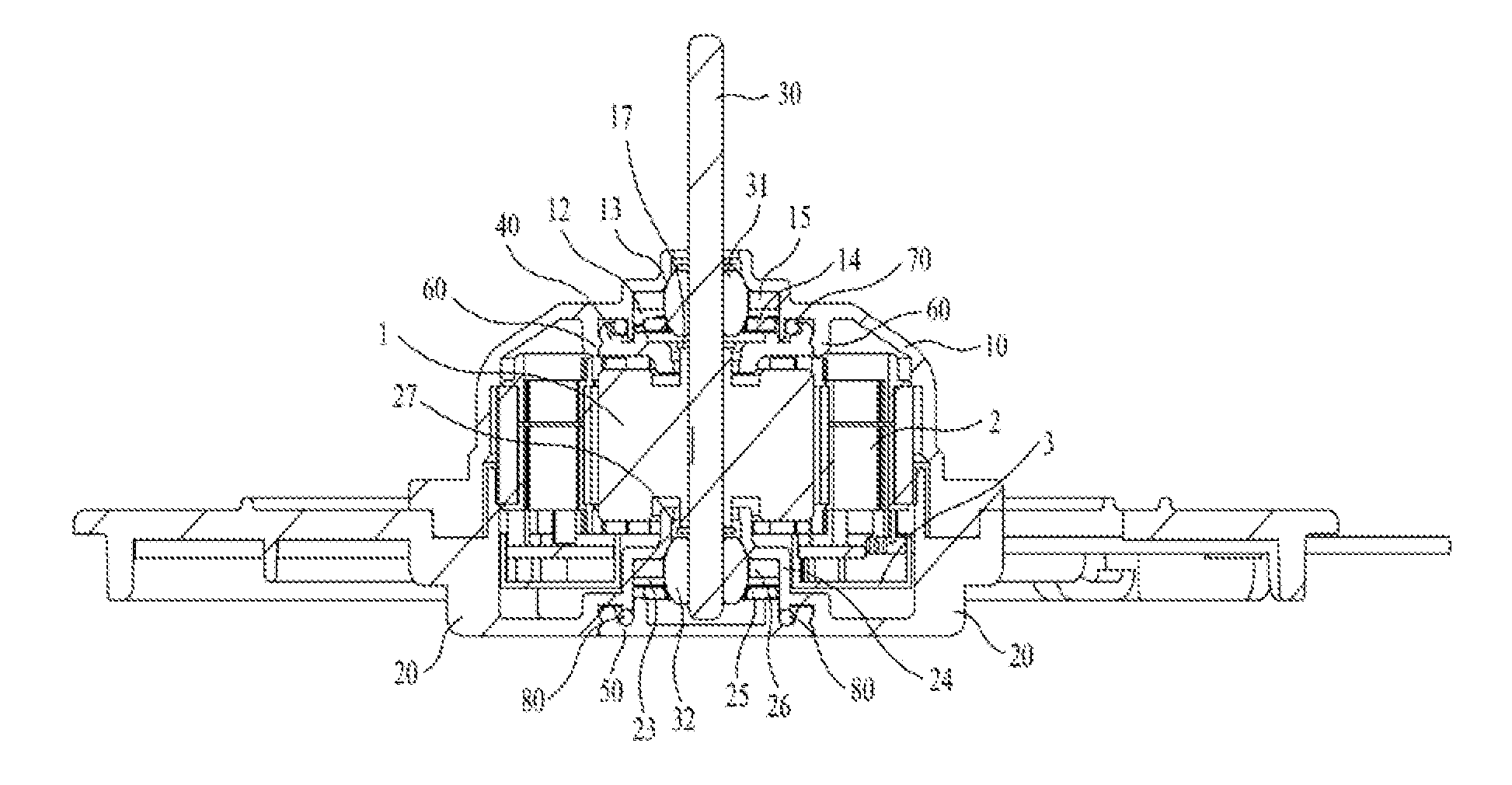
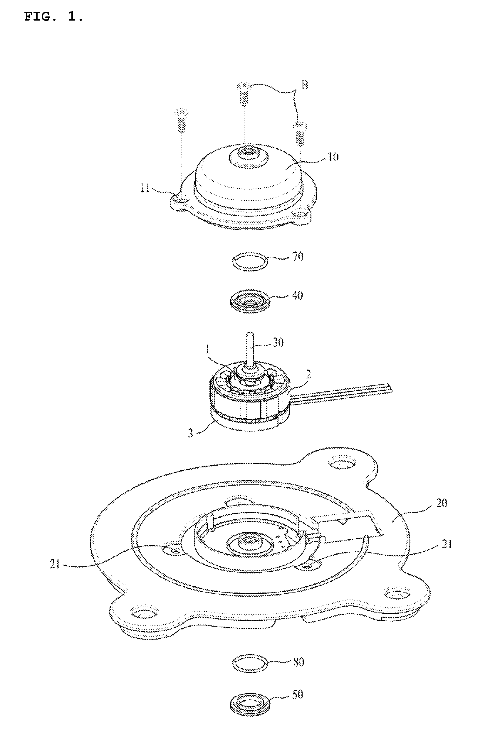
[0030]FIG. 1 is an exploded perspective view of a fan motor according to a preferred embodiment of the present invention, and FIG. 2 is a sectional view of a cut part of the fan motor.

[0031]As shown in FIGS. 1 and 2, the fan motor according to the preferred embodiment of the present invention includes a first bracket 10, a second bracket 20, a rotary shaft 30, an upper felt cover 40, and a lower felt cover 50.

[0032]The first bracket 10 and the second bracket 20 are manufactured by plastic injection molding and are screw-coupled with each other by bolts (B). For this, screw holes 11 and 21 to which the bolts (B) are inserted are respectively formed in the outer circumferential surfa...


PUM


Abstract

Disclosed is a fan motor includes: a first bracket having a middle part through which a rotary shaft penetrates and an upper bearing insertion space to which an upper bearing is inserted to support the upper end part of the rotary shaft; an upper felt cover joined to the inside of the first bracket to seal the upper bearing insertion space; a second bracket joined to the upper side of the first bracket, the second bracket having a lower bearing insertion space which is formed at the middle part of the lower side through which the rotary shaft penetrates and to which a lower bearing is inserted to support the lower end part of the rotary shaft; and a lower felt cover joined to the lower side of the second bracket to seal the lower bearing insertion space.

Description

CROSS REFERENCE TO PRIOR APPLICATIONS[0001]This application claims priority under 35 U.S.C. §119 to Korean Patent Application No. KR 10-2013-0161663 filed on Dec. 23, 2013, which is hereby incorporated by reference in its entirety.BACKGROUND OF THE INVENTION[0002]1. Field of the Invention[0003]The present invention relates to a fan motor, and more particularly, to a fan motor which can reduce processing time because an assembling process is simple and effectively prevent oil leakage from a motor housing.[0004]2. Background Art[0005]In general, a motor used to blow cold air of a refrigerator or circulate inside air and outside air of a device is called a fan motor. Such a fan motor is generally installed in a humid place or in the environment where dew condensation is caused due to a change in temperature. Therefore, because permeation of moisture to the inside of the motor may cause malfunction of the motor, various structures of the motor for preventing such a problem have been stu...

Claims


Application Information

Patent Timeline
Patent Type & Authority Patents(United States)
IPC IPC(8): H02K5/04H02K5/173H02K5/167H02K5/16F04D29/64F04D29/62F04D29/063H02K7/14
CPCH02K5/173H02K5/16H02K5/1672H02K5/167H02K5/04F04D29/063F04D29/626F04D29/646H02K7/14
Inventor JANG, JEONG CHEOLPARK, GYEONG SUCHO, WOO SUNG
Owner NEW MOTECH
Why Eureka
Try Eureka