Vacuum cleaner tool

a vacuum cleaner and tool technology, applied in the direction of suction cleaners, cleaning equipment, suction nozzles, etc., can solve the problem of not being able to draw bristles into the suction opening, and achieve the effect of effective sealing, increased coverage of the strip of bristles, and no compromise in the pickup performance of the tool

Active Publication Date: 2016-08-23
DYSON TECH LTD
View PDF50 Cites 2 Cited by
  • Summary
  • Abstract
  • Description
  • Claims
  • Application Information

AI Technical Summary

Benefits of technology

[0006]The bristles that protrude beyond the carrier therefore have a length that is smaller than the width of the wings. As a result, is not possible for the bristles to be drawn up into the suction opening. In particular, the wings prevent the bristles from being drawn up into the suction opening. As a result, relatively fine and soft bristles may be used. By attaching the bristles to a carrier that pivots or flexes, the bristles are required to bend through a smaller angle. The bristles are therefore subjected to smaller stresses, thus improving the longevity of the bristles. Additionally, the bristles are better able to retain their shape.
[0014]By attaching the bristles to a carrier that pivots or flexes, the bristles are required to bend through a smaller angle. The bristles are therefore subjected to smaller stresses, thus improving the longevity of the bristles. Additionally, the bristles are better able to retain their shape. The wings may also help to prevent the bristles from being drawn up into the suction opening. By contacting one of the two edges of the nozzle as the tool is swept forwards and backwards, the carrier proves an effective seal against the nozzle. Consequently, the pickup performance of the tool is not compromised by the provision of the carrier.

Problems solved by technology

As a result, is not possible for the bristles to be drawn up into the suction opening.

Method used


Image

  • Vacuum cleaner tool
  • Vacuum cleaner tool
  • Vacuum cleaner tool

Examples


Embodiment Construction

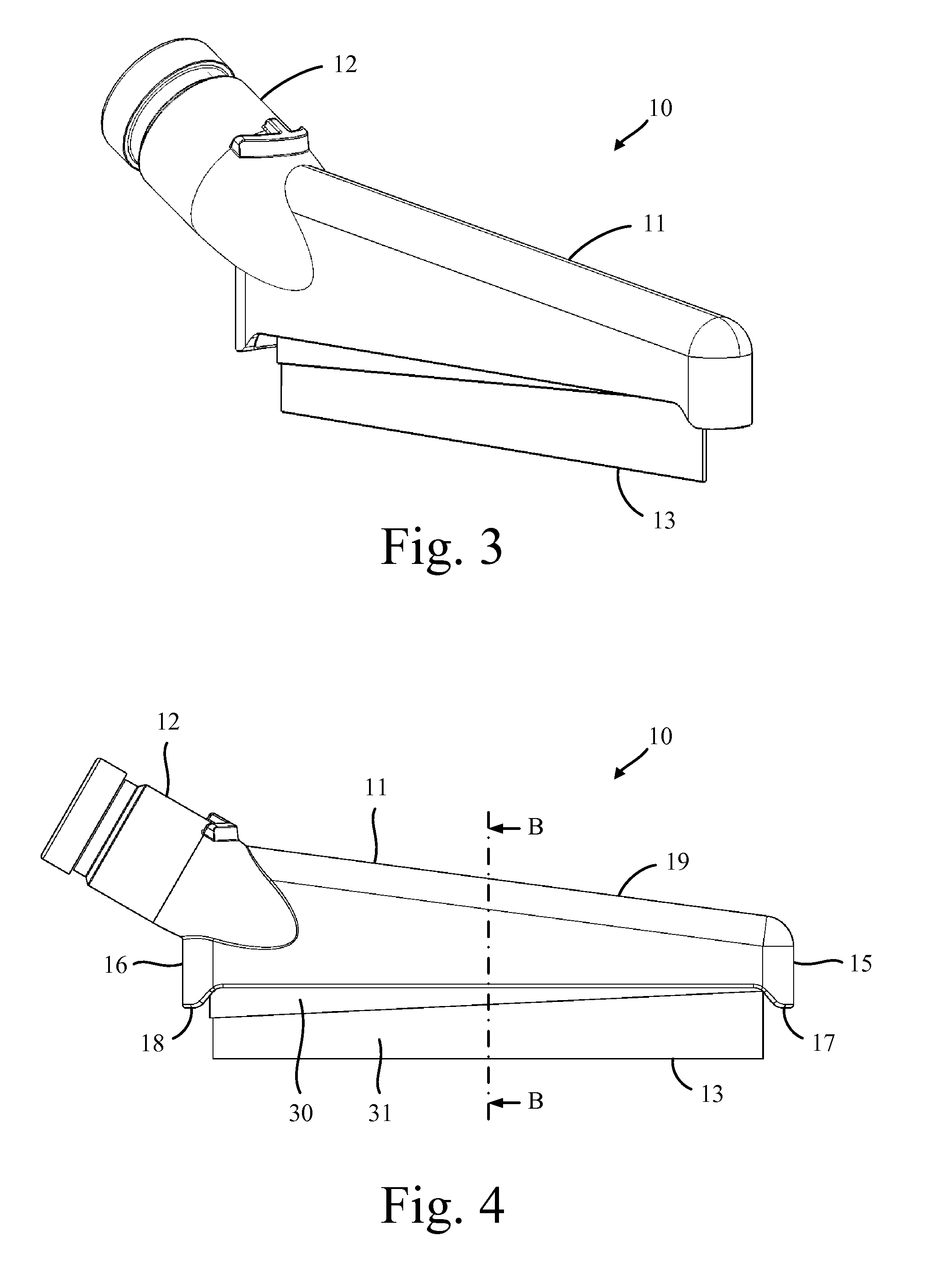
[0038]The vacuum cleaner tool 10 of FIGS. 3 to 8 comprises a nozzle 11, a connecting duct 12, and a bristle assembly 13.

[0039]The nozzle 11 is a relatively narrow structure, with the width of the nozzle 11 being much smaller than the length of the nozzle 11. The height of the nozzle 11 tapers (i.e. decreases gradually) from the rear 16 to the front 15 of the nozzle 11, the advantages of which are explained below. The nozzle 11 comprises a suction opening 20 that opens up into an internal cavity 21 within the nozzle 11. The suction opening 20 is located in the base of the nozzle 11 and extends centrally from the front 15 to the rear 16 of the nozzle 11. The suction opening 20 is delimited along its length by two edges 22,23 of the nozzle 11. Each edge 22,23 is raised relative to the lower ends 17,18 of the front 15 and the rear 16 of the nozzle 11. Consequently, when the base of the nozzle 11 is brought into contact with a cleaning surface 40, a gap 25 is created between each of the ...


PUM


Abstract

A tool for a vacuum cleaner that includes a nozzle and a bristle assembly. An elongate suction opening is provided in a base of the nozzle. The bristle assembly is mounted within the nozzle and includes a carrier to which a strip of bristles is attached. The carrier pivots or flexes relative to the nozzle and has a pair of wings located on opposite sides of the bristles.

Description

REFERENCE TO RELATED APPLICATION[0001]This application claims priority of United Kingdom Application No. 1402281.8, filed Feb. 10, 2014, the entire contents of which are incorporated herein by reference.FIELD OF THE INVENTION[0002]The present invention relates to a tool for a vacuum cleaner.BACKGROUND OF THE INVENTION[0003]FIGS. 1 and 2 illustrate a known type of vacuum cleaner tool 1. The tool 1 comprises a nozzle 2 having an elongate suction opening 3, and a strip of the bristles 4 that protrude through the suction opening 3. The tool 1 is intended to be swept from side-to-side in directions normal to the suction opening 3. As the tool 1 is swept forwards, the bristles 4 bend backwards and contact the trailing edge of the nozzle 2. The suction opening 3 is therefore located in front of the bristles 4 irrespective of the direction of travel.[0004]A problem with the tool 1 is that the bristles 4 must be relatively stiff in order to avoid the bristles 4 being drawn up into the nozzle...

Claims


Application Information

Patent Timeline
Patent Type & Authority Patents(United States)
IPC IPC(8): A47L9/06
CPCA47L9/0666A47L9/062A47L9/0673A47L9/0693
Inventor VENTRESS, SEANMCVEIGH, BRIANCOLE, SAMUEL STEVENGAMMACK, PETER DAVIDDYSON, JAMESSTREETER, ROBERT
Owner DYSON TECH LTD
Why Eureka
Try Eureka