Position measurement correction using loop-closure and movement data

a technology of position measurement and loop closure, applied in the direction of instruments, navigation instruments, sextants, etc., can solve the problems of not being able to determine the position information of components within the cargo bay of the aircraft, the position determination system may not be useful to determine position information, and the limited range of line-of-sight measurements of certain position determination systems

Active Publication Date: 2016-08-23
THE BOEING CO
View PDF21 Cites 13 Cited by
  • Summary
  • Abstract
  • Description
  • Claims
  • Application Information

AI Technical Summary

Benefits of technology

[0006]In another particular embodiment, a non-transitory computer-readable storage medium includes instructions that, when executed by a processor, cause the processor to initialize an inertial measurement unit (IMU) at a starting location, to gather acceleration data as the IMU is moved to an intermediate location, to receive an indication that the IMU is at the intermediate location, and to gather acceleration data as the IMU is moved to an ending location. Th

Problems solved by technology

Certain position determination systems are limited to line-of-sight measurements.
These position determination systems may not be useful to determine position information in interior or other occluded areas of the structure being assembled or maintained.
For example, a laser-based system that is oriented to determine the position of the wings of an aircraft may not be able to also determine positions of components within a cargo bay of the aircraft.
Certain positioning systems, such as laser positioning systems, may be limited to uses that are in a direct line-of-sight to a position sensing device.
Accordingly, positions inside the target structure may be difficult to determine.

Method used


Image

  • Position measurement correction using loop-closure and movement data
  • Position measurement correction using loop-closure and movement data
  • Position measurement correction using loop-closure and movement data

Examples


Embodiment Construction

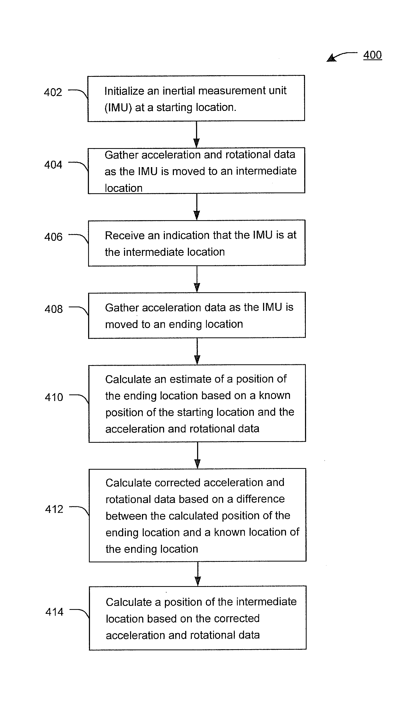
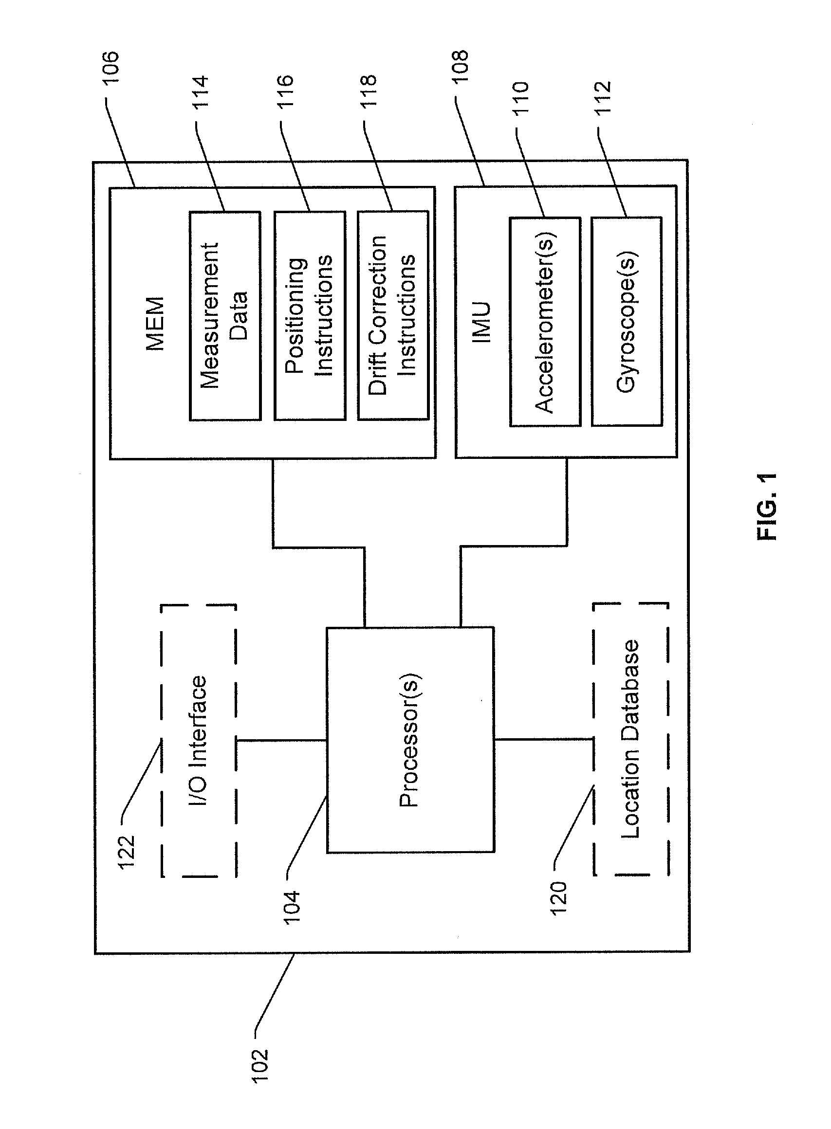
[0017]The present disclosure relates to correcting errors in positions determined based on linear acceleration and rotational rate data measured by an inertial measurement unit (IMU). The IMU may be a component of a portable device that interacts with a positioning system to determine position information at locations where the positioning system cannot independently determine the position information due to, for example, access, expense, time, capacity, or functional limitations of the positioning system. The portable device may be useful for maintenance or assembly of large-scale structures, such as aircraft, watercraft, land craft, space craft, oil platforms, heavy equipment, or other repositionable or stationary structures. Such target structure may be assembled in facilities that use positioning systems to improve precision, accuracy or speed of an assembly or maintenance process. Certain positioning systems, such as laser positioning systems, may be limited to uses that are in...


PUM


Abstract

A method includes initializing an inertial measurement unit (IMU) at a starting location and gathering acceleration and rotational data as the IMU is moved to an intermediate location. An indication that the IMU is at the intermediate location is received. The method includes gathering acceleration and rotational data as the IMU is moved to an ending location and calculating a position of the ending location based on a known position of the starting location and the acceleration data. The method includes calculating corrected acceleration data based on a difference between the calculated position of the ending location and a known position of the ending location, and calculating a position of the intermediate location based on the corrected acceleration data are provided.

Description

CLAIM OF PRIORITY[0001]This application is a continuation-in-part of and claims priority to U.S. patent application Ser. No. 12 / 640,211, filed on Dec. 17, 2009 and entitled “POSITION AND ORIENTATION DETERMINATION USING MOVEMENT DATA,” the contents of which are incorporated herein by reference in their entirety.FIELD OF THE DISCLOSURE[0002]The present disclosure is generally related to position and orientation determination using movement data.BACKGROUND[0003]Assembly and maintenance of large objects, such as repositionable structures, may be assisted by the use of positioning systems to guide placement of components. For example, aircraft may be assembled in facilities that include position determination systems and equipment to measure the position of certain components of the aircraft, such as wings and empennage, to ensure proper placement of the components. Other large-scale assembly facilities may use similar position determination systems. Certain position determination system...

Claims


Application Information

Patent Timeline
IPC IPC(8): G01C17/38G01C1/10G01C21/16F41G7/34G01C25/00B64F5/00G01S5/16
CPCG01C25/005G01S5/16G01C21/16G01C1/10F41G7/343B64F5/00F41G7/34G01C21/188
Inventor TROY, JAMES J.
Owner THE BOEING CO
Why Eureka
Try Eureka