Insulated wire, and electric/electronic equipments, motor and transformer using the same

a technology of insulated wire and electric/electronic equipment, which is applied in the direction of insulating conductors/cables, cables, insulated conductors, etc., can solve the problems of low voltage decay of connection cables, and achieve the effects of improving insulation properties, reducing the thickness of insulating films, and increasing the space factor of wires

Active Publication Date: 2016-08-23
ESSEX FURUKAWA MAGNET WIRE LLC
View PDF21 Cites 7 Cited by
  • Summary
  • Abstract
  • Description
  • Claims
  • Application Information

AI Technical Summary

Benefits of technology

[0018]The present invention can provide an insulated wire having reduced the thickness of an insulating film thereby to increase a space factor of the wire and further having improved an insulation property at a corner portion of a rectangular wire, while maintaining a high partial discharge inception voltage, and an electric / electronic equipment, a motor and a transformer, using the foregoing insulated wire. In the specification, the term “rectangular wire” represents a conductor having a rectangular cross-section or an insulated wire having a rectangular cross-section.
[0019]In particular, the insulated wire of the present invention has a foamed layer composed of a thermosetting resin incorporating therein bubbles on a conductor having a rectangular shaped cross-section, and the relative dielectric constant of an insulated film at a flat portion is less than 3, so that a partial discharge inception voltage is high. Further, in the insulated wire of the present invention, by satisfying the above-described relationship represented by the specific formula between the thickness and the relative dielectric constant of the insulating film at the flat portion and the corner portion, an insulation property at the corner portion are enhanced, so that reduction in the partial discharge inception voltage at the corner portion can be suppressed. In addition, by satisfying a relationship represented by formula: (T1 / ∈1)>15, the partial discharge inception voltage can be further increased.
[0020]On the other hand, in the insulated wire of the present invention, the presence of the non-foamed layer(s) containing no bubble, on the inner periphery and / or the outer periphery of the foamed layer enables an improvement in a dielectric breakdown property, a tensile strength and an abrasion resistance of the insulating film. Further, the insulated wire of the present invention is excellent in heat resistance due to adoption of a polyamideimide resin and / or a polyimide resin as the resin of the foamed layer.
[0021]Further, by disposing an extruded layer composed of a resin having a particular relative dielectric constant and a particular melting point for the outermost layer of the insulating layer, the thickness of the insulating layer can be enlarged without deteriorating a relative dielectric constant and a heat resistance of the insulating layer, and also a partial discharge inception voltage can be further increased.
[0022]For this reason, a winding composed of the insulated wire of the present invention allows the production of a coil having a high space factor, so that the winding can be favorably used for high-performing motors and transformers.
[0023]Other and further features and advantages of the invention will appear more fully from the following description, appropriately referring to the accompanying drawings.

Problems solved by technology

However, the inverters are switched at a frequency of several kHz to tens of kHz, to cause a surge voltage at every pulse thereof.
Accordingly, even if a connection cable is short, the surge voltage is high, and further, voltage decay due to the connection cable is low.

Method used


Image

  • Insulated wire, and electric/electronic equipments, motor and transformer using the same
  • Insulated wire, and electric/electronic equipments, motor and transformer using the same
  • Insulated wire, and electric/electronic equipments, motor and transformer using the same

Examples


example 1

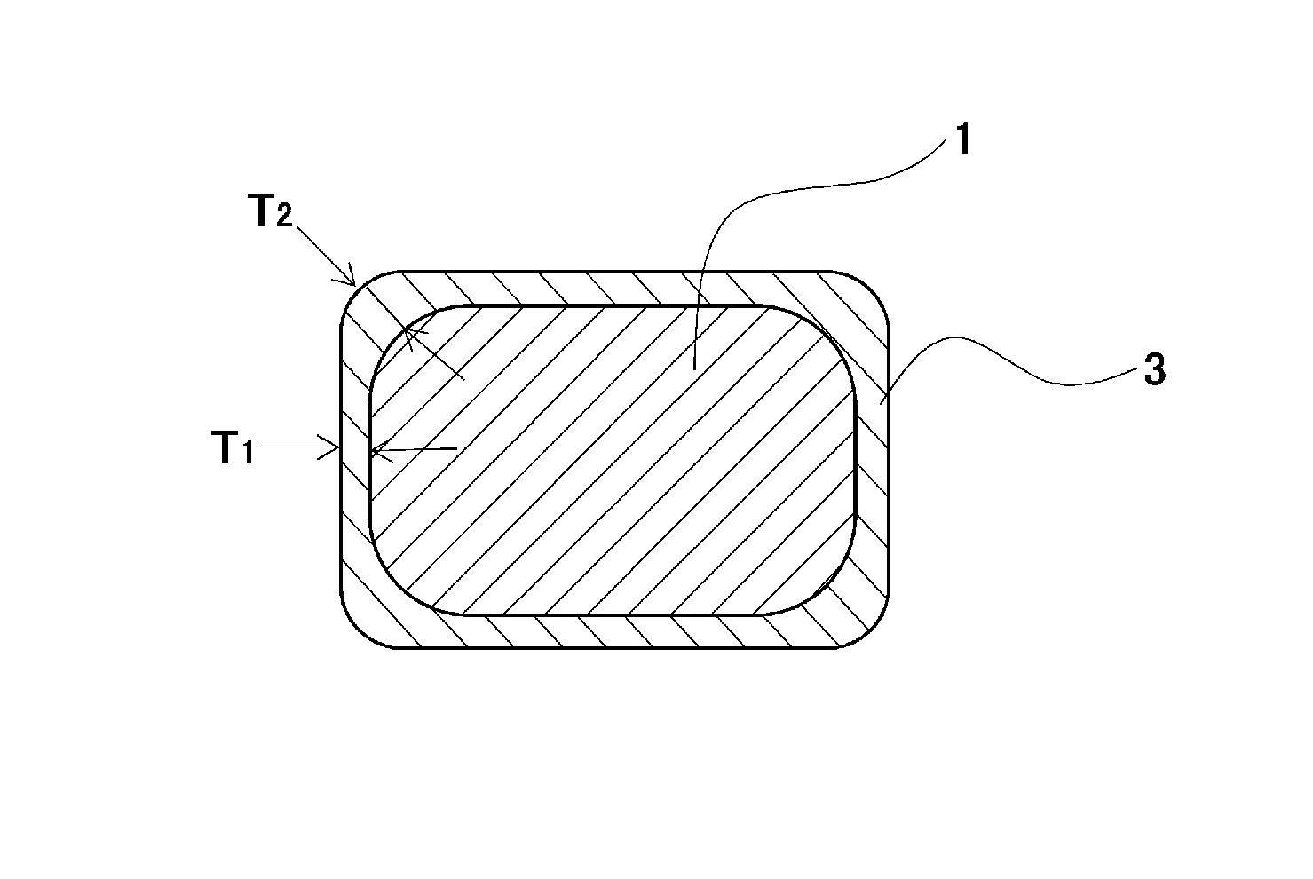
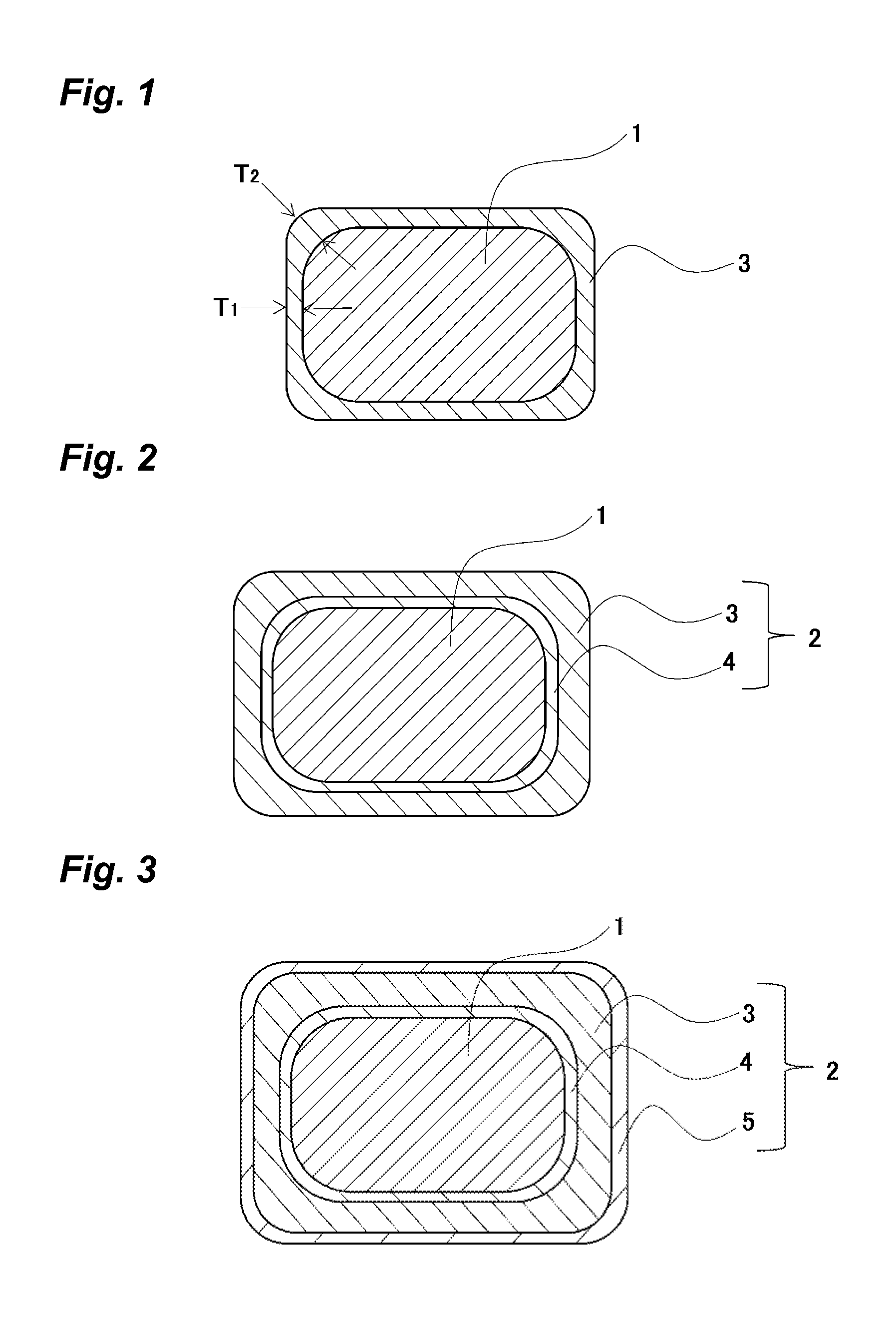
[0104]An insulated wire shown in FIG. 1, having a foamed layer of the above PAI on the above conductor, was produced. Specifically, the foamable PAI varnish was coated to the conductor by means of a universal die having a curvature radius r=0.2 mm at the connection point between a longitudinal side and a transverse side of the universal die and then baking the varnish at a furnace temperature of 520° C. for 20 sec. per once, and then this process was repeated eight times, thereby forming the foamed layer of the above PAI, thereby obtaining an insulated wire of Example 1.

example 2

[0105]An insulated wire shown in FIG. 2, having an inner non-foamed layer of the above PI and a foamed layer of the above PI on the above conductor, was produced. Specifically, the PI varnish was coated to the conductor by means of a universal die having a curvature radius r=0.3 mm at the connection point between a longitudinal side and a transverse side of the universal die and then baking the varnish at a furnace temperature of 520° C. for 20 sec. per once, and then this process was repeated four times, thereby forming the inner non-foamed layer of the above PI, and then baking the PI varnish thereon eight times, thereby forming the foamed layer of the above PI, thereby obtaining an insulated wire of Example 2.

example 3

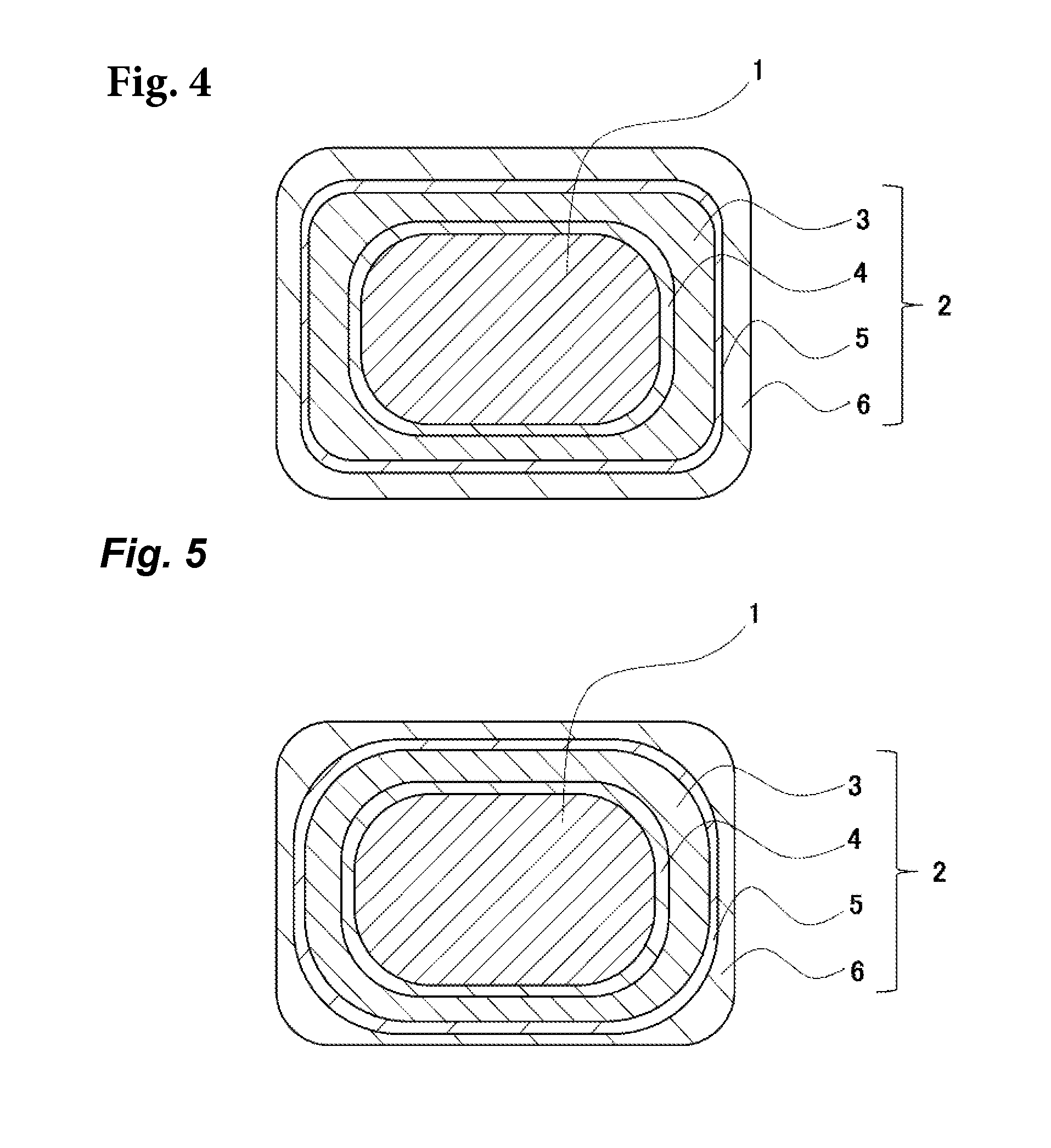
[0106]The insulated wire shown in FIG. 3, having an inner non-foamed layer of the above PAI, a foamed layer of the above PAI, and an outer non-foamed layer of the above PI on the above conductor, was produced. Specifically, the PAI varnish was coated to the conductor by means of a universal die having a curvature radius r=0.4 mm at the connection point between a longitudinal side and a transverse side of the universal die and then baking the varnish at a furnace temperature of 520° C. for 20 sec. per once, and then this process was repeated two times, thereby forming the inner non-foamed layer of the above PAI, and then baking the formable PAI varnish thereon eight times, thereby forming the foamed layer of the above PAI, and further baking the PI varnish thereon six times, thereby forming the outer non-foamed layer of the above PI, thereby obtaining an insulated wire of Example 3.


PUM

PropertyMeasurementUnit
melting pointaaaaaaaaaa
relative dielectric constantaaaaaaaaaa
dielectric constantaaaaaaaaaa

Abstract

An insulated wire having a rectangular shaped cross-section, containing: a conductor having a rectangular shaped cross-section; and an insulating layer coated on the conductor, in which the insulating layer has a foamed layer composed of a thermosetting resin containing bubbles, the cross-section of the insulating layer has a shape composed of a flat portion and a corner portion, and the insulating layer satisfies the relationship represented by the following formula:∈1<3 and (T2 / ∈2)>(T1 / ∈1)wherein T1 [μm] represents a thickness of the flat portion; ∈1 represents a relative dielectric constant of the flat portion; T2 [μm] represents a thickness of the corner portion; and ∈2 represents a relative dielectric constant of the corner portion, and an electric / electronic equipment, a motor, or a transformer, using the insulated wire.

Description

CROSS-REFERENCE TO RELATED APPLICATIONS[0001]This application is a continuation of PCT / JP2014 / 061282 filed on Apr. 22, 2014 which claims benefit of Japanese Patent Application No. 2013-094724 filed on Apr. 26, 2013, the subject matters of which are incorporated herein by reference in their entirety.TECHNICAL FIELD[0002]The present invention relates to an insulated wire, and electric / electronic equipments, a motor and a transformer using the same.BACKGROUND ART[0003]Inverters have been installed in many types of electric equipment such as a motor used in a vehicle, as an efficient variable-speed control unit. However, the inverters are switched at a frequency of several kHz to tens of kHz, to cause a surge voltage at every pulse thereof. Inverter surge is a phenomenon in which reflection occurs at a breakpoint of impedance, for example, at a starting end, a termination end, or the like of a connected wire in a propagation system, and as a result, a voltage up to twice as high as an i...

Claims


Application Information

Patent Timeline
Patent Type & Authority Patents(United States)
IPC IPC(8): H01F27/30H01B7/02H01F27/02H02K3/30H01F5/06H02K3/34H01B7/00H01F27/28H01B13/06H01B3/30
CPCH02K3/34H01F27/2823H01F5/06H02K3/30H01B3/303H01B3/306H01B7/0009H01B7/0216H01B7/0283H01B13/065H01F27/02H01F27/30H01B3/308
Inventor OYA, MAKOTOMUTO, DAISUKETOMIZAWA, KEIICHI
Owner ESSEX FURUKAWA MAGNET WIRE LLC
Why Eureka
Try Eureka