
Surgical cutting system and method

a cutting system and surgical technology, applied in the field of surgical cutting systems, can solve the problems of not teaching a power operated cutting system, not recommending removal, and patients requiring spinal fusion to have severe pain or neurological deficits, and achieve the effect of overcompensating the drawbacks

Active Publication Date: 2016-08-30
ZEGIST SOLUTIONS LLC
View PDF6 Cites 4 Cited by
  • Summary
  • Abstract
  • Description
  • Claims
  • Application Information

AI Technical Summary

Benefits of technology

The present invention aims to improve the performance of surgical cutting systems by combining convenience and utility. The new system should be easy to use and prevent accidental injury to patients.

Problems solved by technology

Patients requiring spinal fusion have either neurological deficits or severe pain which has not responded to conservative treatment.
However, most surgeons do not recommend removal unless the pedicle screws cause discomfort for the patient.
However, the prior art does not teach a rod cutter which is power operated and can be used in the surgery area in very tightly controlled manner.

Method used


Image

  • Surgical cutting system and method
  • Surgical cutting system and method
  • Surgical cutting system and method

Examples


Embodiment Construction

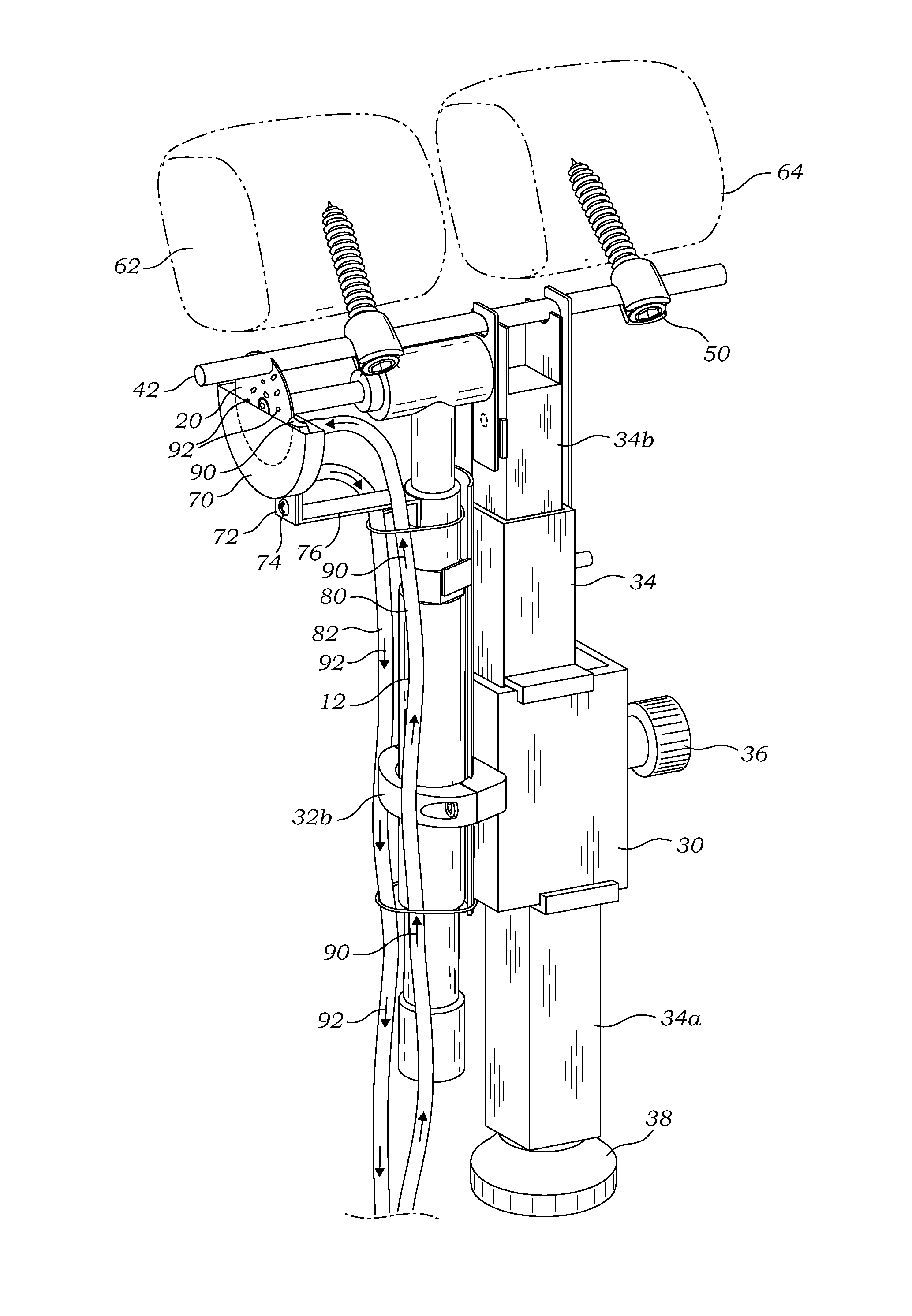
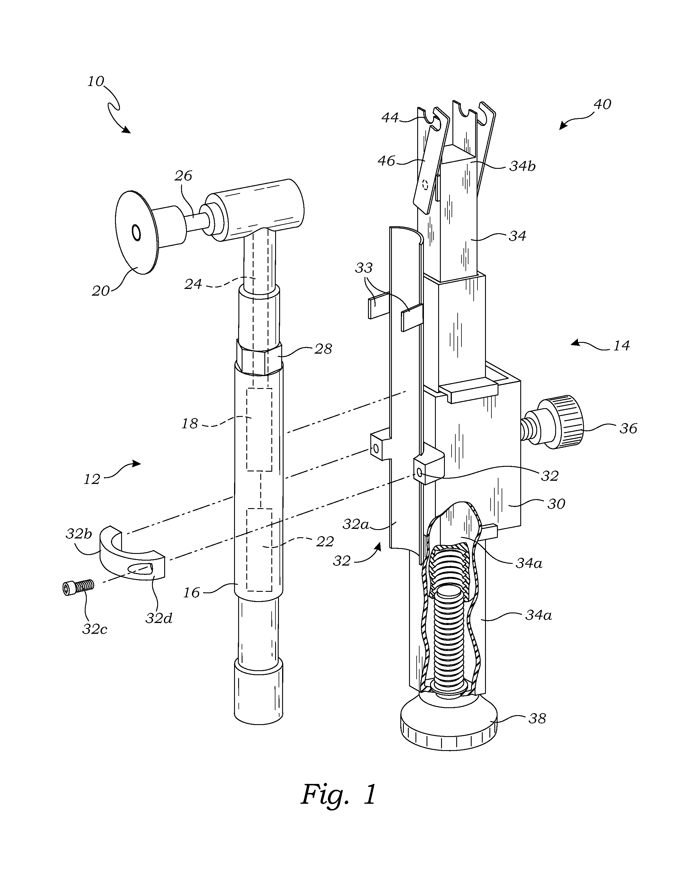
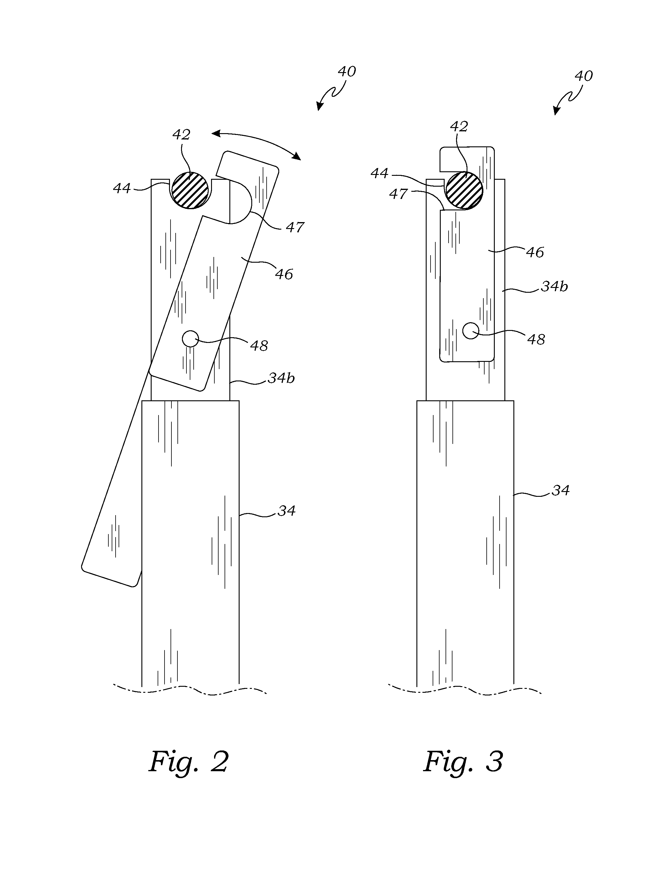
[0036]FIG. 1 is an exploded perspective view of a surgical cutting system 10 according to one embodiment of the present invention. The surgical cutting system 10 is used for cutting a rod (shown in FIG. 2) as part of spinal fusion surgery, as discussed in greater detail below. The surgical cutting system 10 comprises a rod cutting tool 12 and a guide device 14 for guiding the rod cutting tool 12 for making a controlled cut of the rod.

[0037]In the present embodiment, the rod cutting tool 12 includes a housing 16 containing a drive motor 18 and a cutting element 20 operably mounted on the housing 16 and operably connected to the drive motor 18. The housing 16 further includes a power source 22 to provide power to the drive motor 18 and a transmission 24 to transfer the rotary motion from the drive motor 18 to the cutting element 20. In one embodiment the rod cutting tool 12 is a rotary cutting tool, and the cutting element 20 is a cutting disk, however in alternative embodiments the c...


PUM


Abstract

A surgical cutting system has a rod cutting tool and a guide device. The rod cutting tool includes a housing containing a drive motor and a cutting element mounted on the housing connected with the drive motor. The guide device includes a guide body, an attachment mechanism for attaching the rod cutting tool to the guide body, an elongate body movably mounted on the guide body, a rod-clamping element operably mounted on the elongate body, to lockingly engage the rod during the spinal fusion surgery and position the cutting element adjacent the rod. The cutting system also includes an adjustment mechanism for moving the elongate body relative to the guide body thereby moving the cutting element to cut the rod.

Description

FIELD OF THE INVENTION[0001]The present invention relates generally to rod cutting systems, and more particularly to surgical cutting system for cutting a rod used for spinal fixation in a patient's body.BACKGROUND OF THE INVENTION[0002]In a human body the spinal column encloses the spinal cord and consists of a number of bones (called vertebrae) superimposed upon one another in a series which provides a flexible supporting column for the trunk and head. There are normally thirty-three vertebrae in humans, including the five that are fused to form the sacrum and the four coccygeal bones that form the tailbone. The upper three regions comprise the remaining twenty-four, and are grouped under the names cervical (seven vertebrae), thoracic (twelve vertebrae) and lumbar (five vertebrae), according to the regions they occupy.[0003]Spinal fusion is a surgical technique in which one or more of the vertebrae of the spine are united together so that motion no longer occurs between them. Spin...

Claims


Application Information

Patent Timeline
Patent Type & Authority Patents(United States)
IPC IPC(8): A61B17/88
CPCA61B17/8863
Inventor MCVEAN, DOVIEMCVEAN, GARYMCVEAN, JAMES
Owner ZEGIST SOLUTIONS LLC
Learn More