Method and device for lubricating the cylinders of a roll stand

a technology of lubricating cylinder and roll stand, which is applied in the direction of work lubrication devices, metal rolling arrangements, manufacturing tools, etc., can solve the problems of reducing the lubrication efficiency of the cylinder, the inability to provide hot water to the mixing unit or the connecting line, and the inability to use the nozzle. , to achieve the effect of reducing the saponification, reducing the calcification of the heating elements, and reducing the saponification

Inactive Publication Date: 2016-09-06
PRIMETALS TECH AUSTRIA GMBH
View PDF14 Cites 1 Cited by
  • Summary
  • Abstract
  • Description
  • Claims
  • Application Information

AI Technical Summary

Benefits of technology

[0009]According to a fundamental idea of the invention, the hot water used for cleaning purposes is produced by a heating device, which heats the water flowing into the water supply line, heating it virtually in line. This heating device is permanently installed but is only active for a time interval which is predetermined by a control device. As a result, a third supply line which supplies hot water to the mixing unit or to connecting lines between the mixing unit and nozzle is unnecessary. The constant provision of hot water is likewise unnecessary. The expense of a thermally insulated container for the provision of warm or hot water is spared as a result. This has several advantages. On the one hand, a system for roll nip lubrication can be easily constructed. On the other hand, cleaning of the roll nip lubrication system can be performed more easily. During a short maintenance downtime, the hot water for flushing the mixing unit and nozzles is also available very quickly and its temperature can be adjusted to requirements very easily. This also enables cleaning during short production downtimes so that saponification can be countered at an early stage. Energy can be supplied to the heating device in various ways, for example electrically or using another fuel, e.g. gas or oil.
[0010]In a preferred embodiment, the heating device can be operated electrically, e.g. as an instantaneous water heater. An instantaneous water heater has several advantages. On the one hand, the necessary construction volume for a rolling mill compared with a hot water cylinder is much smaller. The water temperature necessary for cleaning can be very precisely predetermined and adjusted by means of electronic control of the energy supply to the individual resistance heating elements. As a result, the energy requirements can be adjusted to the level of the contamination of the lubrication equipment.
[0012]For efficient cleaning, it may be advantageous if the control unit controls the heating device in such a way that the water flowing to the mixing and spraying device is heated to a predetermined temperature of more than 60° C. and is adjusted to this temperature.
[0013]Saponification of the emulsion can be reduced by means of a permanent water treatment plant installed in the water supply, e.g. an ion exchanger or osmosis plant. In addition, soft water is favorable for an instantaneous electric water heater as there is less calcification on the heating elements.
[0014]In a particularly preferred embodiment provision can be made for the mixing and spraying device to be comprised of a number of nozzle-mixer-units, wherein each nozzle-mixer-unit is supplied with both water and oil separately. In contrast to the prior art, where a mixing device supplies several nozzles, in the present embodiment of the invention, a separate mixing unit is assigned to each nozzle. The design of each nozzle-mixer-unit is structurally compact as a unit and includes both the mixing function and the spraying function. As a result, there are virtually no connecting lines between the mixer and the nozzle in which saponification could occur. The dwell time of the emulsion / dispersion in the unit is very short, resulting in reduced saponification. As a result, the rolling process need not be interrupted as often as with prior art for the purposes of cleaning the roll nip lubrication.
[0015]Maintenance work can be made easier if each of these nozzle-mixer-units can be released from its fixture device by means of a quick release fastener e.g. a bayonet fastening. By this means contaminated units can be changed very quickly during maintenance downtime.

Problems solved by technology

As a result, a third supply line which supplies hot water to the mixing unit or to connecting lines between the mixing unit and nozzle is unnecessary.
The constant provision of hot water is likewise unnecessary.

Method used


Image

  • Method and device for lubricating the cylinders of a roll stand
  • Method and device for lubricating the cylinders of a roll stand
  • Method and device for lubricating the cylinders of a roll stand

Examples


Embodiment Construction

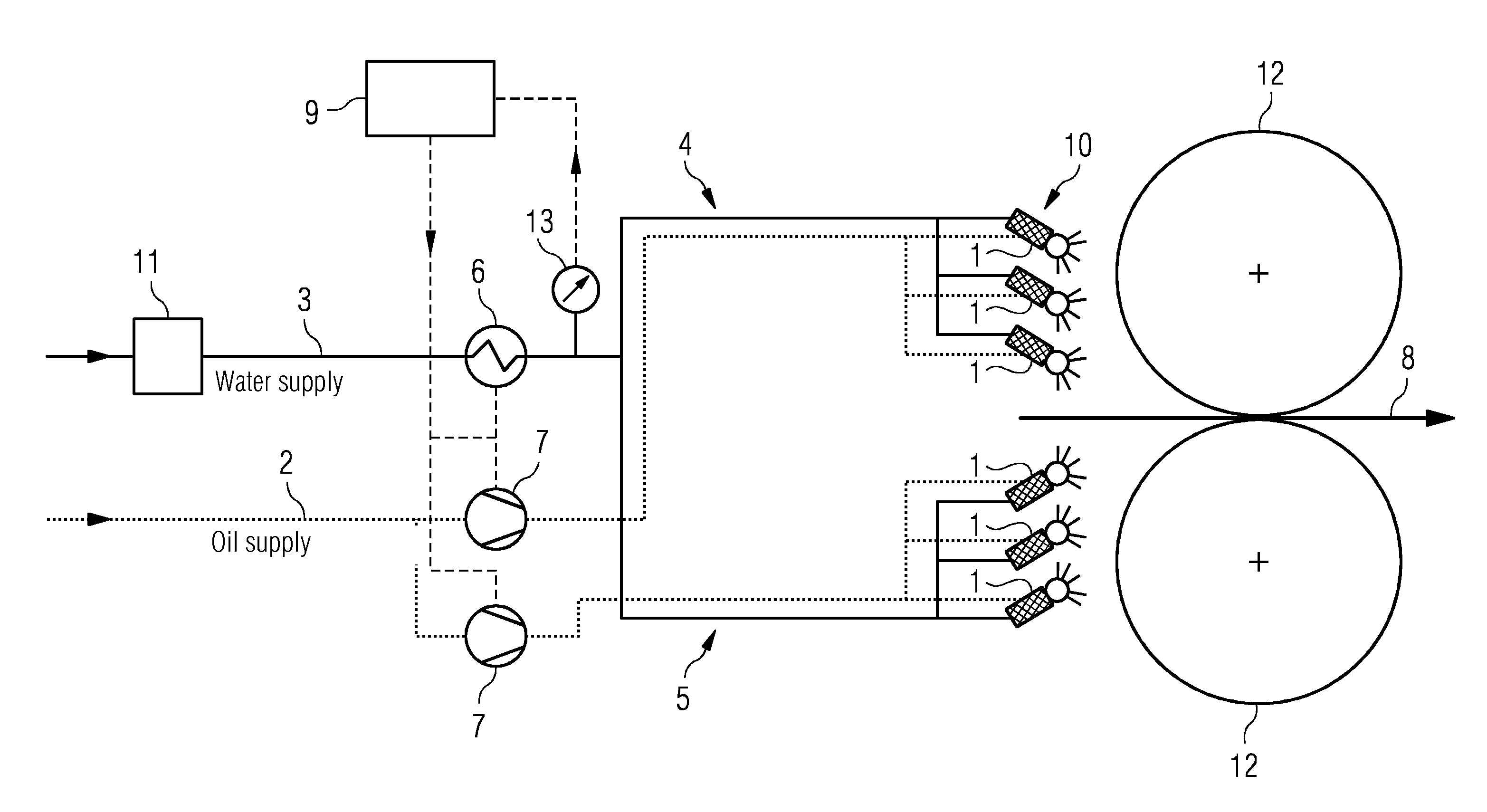
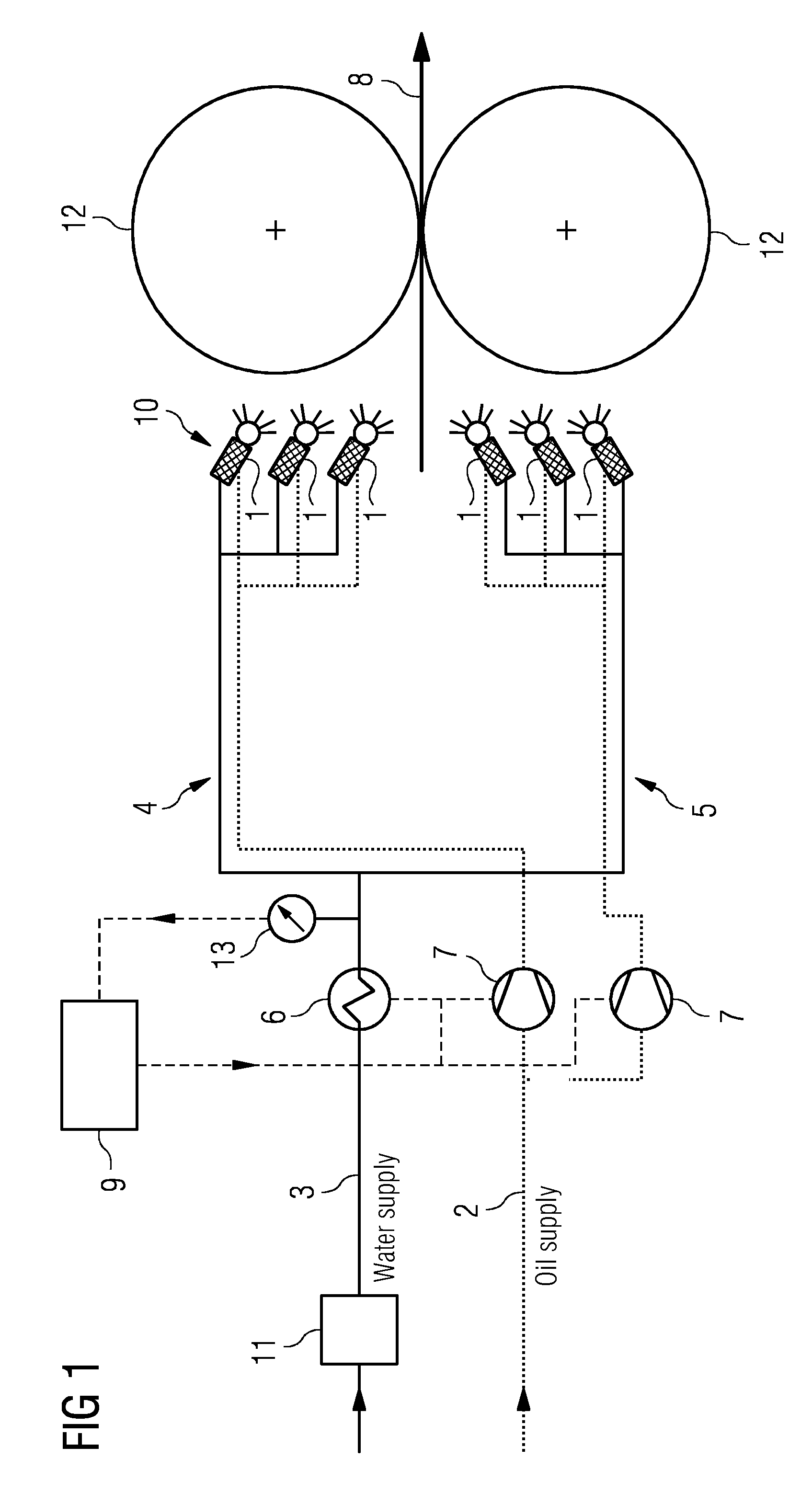
[0019]FIG. 1 shows a diagrammatic view of an exemplary embodiment of the device according to the invention for lubricating the cylinders of a roll stand. For the sake of clarity, only the two cylinders 12 of the roll stand are shown, in the roll nip through which the roll band 8 is rolled. On the inlet side of the cylinders 12, a mixing and spraying device 10 can be seen. This mixing and spraying device 10 is comprised of a number of nozzle-mixer-units 1, each of which is supplied with oil and water. The dispersion is a water-oil mixture, comprised of extremely small oil droplets in water. On the one hand, each of these nozzle-mixer-units 1 operates as a mixer which processes oil and water to form a homogenous emulsion / dispersion. On the other hand, each of these nozzle-mixer-units 1 operates as a spraying unit which introduces the emulsion into the roll nip in the form of a spray. This introduction can take place by spraying in the direction of the roll gap, or in the direction of ...


PUM

PropertyMeasurementUnit
temperatureaaaaaaaaaa
lengthaaaaaaaaaa

Abstract

A method for lubricating the cylinders of a roll stand, for roll nip lubrication in a roll stand for a roll band. A mixture of water and oil is produced by a mixing and spraying device, which is supplied with water by a first supply line (3) and is supplied with oil by a second supply line (2). The mixture is sprayed to the strip and / or into the roll nip and / or to at least one of the cylinders of the roll stand. The water flowing to the mixing and spraying device (10) is heated by a heating device (6) provided in the first supply line (3) for a predetermined period of time set by controlling a control unit (9).

Description

CROSS-REFERENCE TO RELATED APPLICATIONS[0001]The present application is a 35 U.S.C. §§371 national phase conversion of PCT / EP2013 / 052359, filed Feb. 7, 2013, which claims priority of European Patent Application No. 12155480.2, filed Feb. 15, 2012, the contents of which are incorporated by reference herein. The PCT International Application was published in the German language.TECHNICAL FIELD[0002]The invention relates to a method and a device for lubricating the cylinders of a roll stand, in particular for roll nip lubrication in a roll stand for a roll band. A mixture of water and oil is produced by means of a mixing and spraying device. The device is supplied with water by a first supply line and is supplied with oil by a second supply line. The mixture is sprayed onto the strip being rolled and / or into the roll nip and / or onto at least one of the cylinders of the roll stand.PRIOR ART[0003]It is known that for the production of rolling stock, its surface quality can be improved if...

Claims


Application Information

Patent Timeline
Patent Type & Authority Patents(United States)
IPC IPC(8): B21B27/10B21B45/02
CPCB21B27/10B21B45/0251
Inventor BRAIDT, THOMASKARL, REINHARDLEHNER, CHRISTIAN
Owner PRIMETALS TECH AUSTRIA GMBH
Why Eureka
Try Eureka