System for docking a movable platform

a technology for moving platforms and docking systems, which is applied in the direction of programmed manipulators, mechanical apparatus, manufacturing tools, etc., can solve the problems of not being economically feasible to install a robotic device at each working machine, and achieve the effects of convenient placement or positioning of protruding members, fast and efficient, and improved docking procedures

Active Publication Date: 2016-09-06
OPIFLEX AUTOMATION
View PDF13 Cites 2 Cited by
  • Summary
  • Abstract
  • Description
  • Claims
  • Application Information

AI Technical Summary

Benefits of technology

[0010]The docking system according to the invention carries out docking downwards in a direction from the platform and towards the floor. The docking station can be made very thin, for example in the form of a thin plate and positioned on the floor, or recessed in the floor. Preferably, the docking station is plate shaped, i.e. in the form of a docking plate. The docking station is designed so that it can be mounted in level with the floor and without any protruding parts. Thus, the docking station will not be an obstacle in the robot work area, and not in the way for manual operation or when maintaining the machine or work station.
[0034]According to a further embodiment of the invention, the locking member is selected from the group comprising a locking bar, a locking pin, a locking ball, a locking expander, a locking nail and a locking screw, and the receiving member is arranged to receive the locking member and is selected from the group comprising a groove, a hole, a threaded hole, an indent. Different types of locking devices for providing stable locking can be used and easily installed on the platform and the docking station.

Problems solved by technology

It is usually not economically feasible to install a robotic device at each working machine if the working machine has low utilization or the batch sizes are small.
A problem with the docking station disclosed in WO2010 / 043640 is that it is protruding and accordingly becomes an obstacle in the robot work area.

Method used


Image

  • System for docking a movable platform
  • System for docking a movable platform
  • System for docking a movable platform

Examples


Embodiment Construction

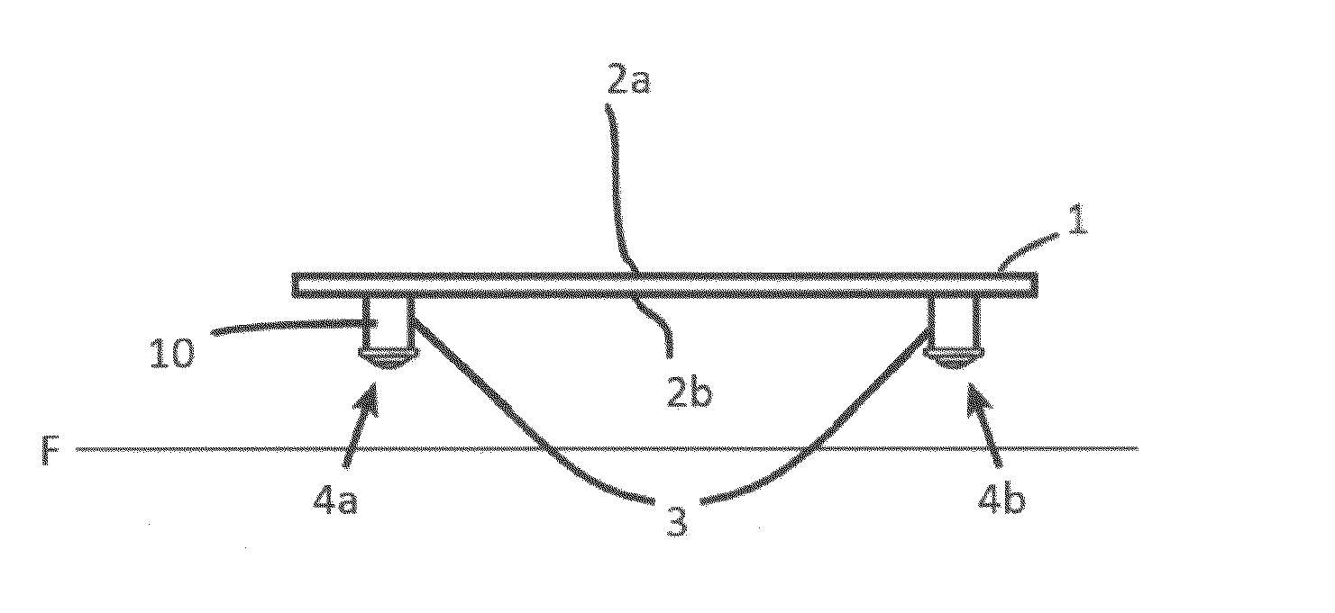
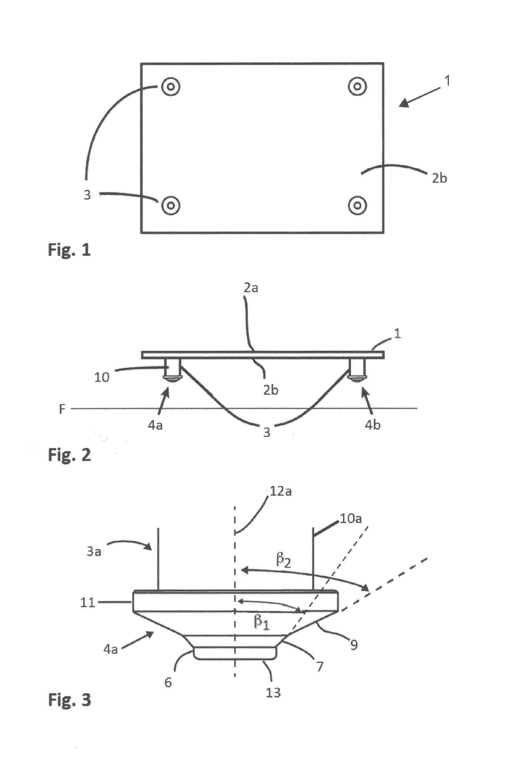
[0046]FIGS. 1 and 2 shows an example of a movable platform 1. FIG. 1 shows a view from below of the platform and FIG. 2 shows a side view of the platform. The movable platform 1 has a top surface 2a and a bottom surface 2b. The surfaces extend along a horizontal plane parallel to a floor F. A plurality of protruding members 3 protrude from the bottom surface of the platform and may be designed as legs supporting the platform. The platform may have two, three or more legs. In this embodiment, the platform is provided with four legs to support the platform. The protruding members 3 may be fixedly attached to the platform. The protruding members 3 may also be linearly movable relative to the platform. The platform may also be provided with wheels. The wheels can be fixed in order to support the platform, or movable relative to the platform.

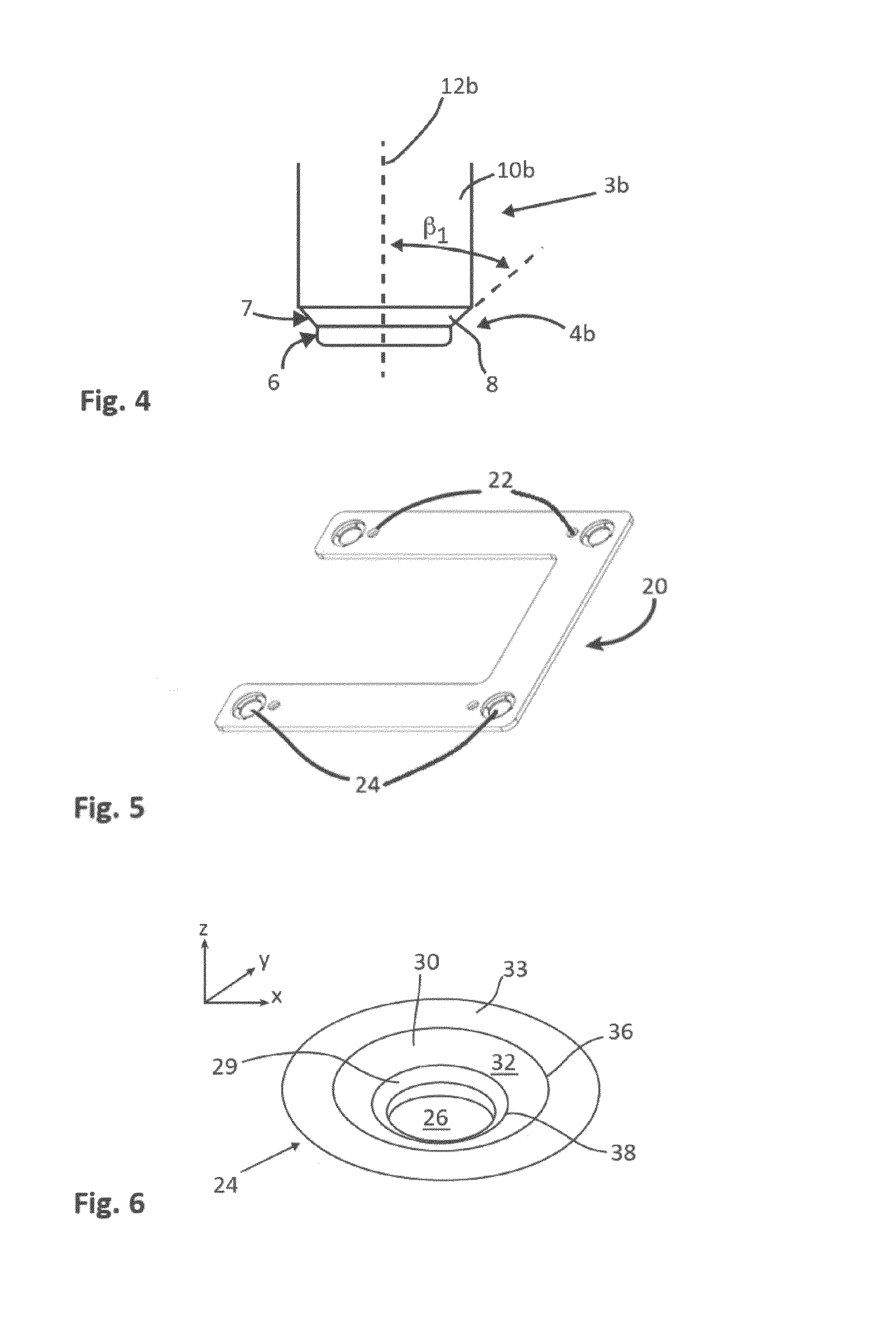
[0047]FIGS. 3 and 4 show two examples of protruding members 3a and 3b. The protruding members 3a-b extend along a central axis 12a, 12b. An outer en...


PUM

PropertyMeasurementUnit
angle α1aaaaaaaaaa
angle α1aaaaaaaaaa
angle α1aaaaaaaaaa

Abstract

A system for docking a platform adapted to carry a manipulator, in relation to a workstation. The system comprises a plurality of protruding members attached to the platform, a docking station arranged at the workstation and comprising a plurality of recesses adapted to receive the protruding members for positioning the platform relative the workstation. Each of the recesses comprises a positioning section defining a space and a supporting section tapering towards the positioning section and having at least one support surface, and the protruding members are protruding away from a bottom surface of the platform, and an outer end of each of the protruding members comprises a positioning portion designed to at least partly fit in said space, and a bearing portion tapering towards the positioning portion and having a bearing surface adapted to bear on the support surface when the positioning portion is fitted in said space.

Description

CROSS-REFERENCE TO RELATED APPLICATIONS[0001]This application claims foreign priority to Swedish Patent Application No. 1450527-5 filed May 5, 2014, entitled “A System For Docking A Movable Platform,” the entire disclosure of which is hereby incorporated by reference in its entirety.FIELD OF THE INVENTION[0002]The present invention relates to a system for docking a movable platform adapted to carry a manipulator, in relation to a workstation. The invention also relates to the use of the docking system.BACKGROUND OF THE INVENTION AND PRIOR ART[0003]In many small factories the manufacturing takes place at different workstations containing one or several fixed machines. Manipulators, such as a robot, tending the machines or performing work tasks can be used in order to increase productivity, cost efficiency, quality or remove monotonous and hazardous work tasks. It is usually not economically feasible to install a robotic device at each working machine if the working machine has low ut...

Claims


Application Information

Patent Timeline
Patent Type & Authority Patents(United States)
IPC IPC(8): B23Q1/00F16B5/06F16B5/00B25J5/00B25J9/10G05D1/02
CPCB25J9/10B23Q1/0063B25J5/00F16B5/0056F16B5/0088F16B5/065Y10T24/45262Y10T29/49899Y10T403/33Y10T403/4694Y10T403/7039F16B2200/10B25J5/007G05D1/02
Inventor FRISK, JOHAN
Owner OPIFLEX AUTOMATION
Why Eureka
Try Eureka