Tibial prosthetic component for a partial or unicondylar bearing knee replacement, method of selecting such a tibial prosthetic component, method of implanting such a tibial prosthetic component and a kit for a surgeon

a tibial prosthetic and knee replacement technology, applied in the field of tibial prosthetic components for partial or unicondylar bearing knee replacement, can solve the problems of bone-on-bone contact, pain, and onset of pain, and no drug-based treatment has been found to stop or reverse these processes, so as to reduce the amount of bone, reduce the effect of weakening the bone, and improve the capacity to handle stress

Active Publication Date: 2013-06-27
OCONNOR JOHN +3
View PDF6 Cites 18 Cited by
  • Summary
  • Abstract
  • Description
  • Claims
  • Application Information

AI Technical Summary

Benefits of technology

[0030]An end of the projection located posteriorly and / or anteriorly, in use, may extend at an angle of less than 90 degrees to a longitudinal direction of the projection. In one embodiment, the end of the projection located posteriorly, in use, is curved, with the radius of curvature being at least 2.0, and possibly approximately 2.5 or 3.0 mm or more. The radius of curvature of the end may be about half the keel depth, which may be between 3.5 mm and 4.5 mm (inclusive). We have found that a higher radius of curvature for the ends of the keel (higher than the current 1.5) gives greater capacity to handle stress, and possibly allows the keel to be made shallower and / or shorter in the anterior-posterior direction. This may be a separate invention. By having a shallower and / or shorter keel we reduce the amount of bone that needs to be removed at the posterior of the tibia, (or anterior) reducing weakening of the bone in this area compared to previous known Oxford tibial prosthetic components having keels.
[0031]The keel may comprise webs extending from the projection to brace the projection against the plate. The webs strengthen the connection of the plate to the projection and / or make the projection more rigid than it would be without the webs, reducing the chance of the projection breaking away or being bent, in use. The webs may also stiffen / reinforce the plate compared to how it would be without the webs, allowing thinner plates to be used. The webs may comprise a continuous brace such that there are no gaps between each web and the projection and the plate. Alternatively, the webs may comprise struts or a continuous brace having holes therein such that there are gaps in or between each web and the projection and / or plate. By providing gaps, over time bone may grow into the gaps further securing the prosthetic component in place. In addition specialist porous coatings which may or may not include Hydroxyapaptite may be added that encourage bony ingrowth.

Problems solved by technology

Damage to the articular surfaces or to the ligaments changes the patterns of movement of the bones on each other and response of the joint to load.
Osteoarthritis follows from failure of the cartilage in one or other of the three joints, leading to bone-on-bone contact and the onset of pain.
No drug-based treatment has been found which halts or reverses these processes.
Partial knee replacement is surgically more demanding and is not always used when it is indicated.
It has been appreciated that, for a person having a small knee joint, cutting away sections of the tibia to make way for the tibial prosthetic component can weaken the bone surrounding the components to such an extent as to cause bone to break off and can also cause ligaments to detach.
In addition, in medial partial knee replacements, removal of too much bone can result in inadvertent damage to the medial collateral ligament, which can result in overstuffing the replaced compartment and overloading the intact lateral compartment, leading to its eventual degeneration.
We have come to realise that having plates of the same depth for large people and small people is wrong.
Also, having keels of the same depth and width can be a problem for small people, and may result in an unnecessarily weakened tibia.

Method used


Image

  • Tibial prosthetic component for a partial or unicondylar bearing knee replacement, method of selecting such a tibial prosthetic component, method of implanting such a tibial prosthetic component and a kit for a surgeon
  • Tibial prosthetic component for a partial or unicondylar bearing knee replacement, method of selecting such a tibial prosthetic component, method of implanting such a tibial prosthetic component and a kit for a surgeon
  • Tibial prosthetic component for a partial or unicondylar bearing knee replacement, method of selecting such a tibial prosthetic component, method of implanting such a tibial prosthetic component and a kit for a surgeon

Examples


Embodiment Construction

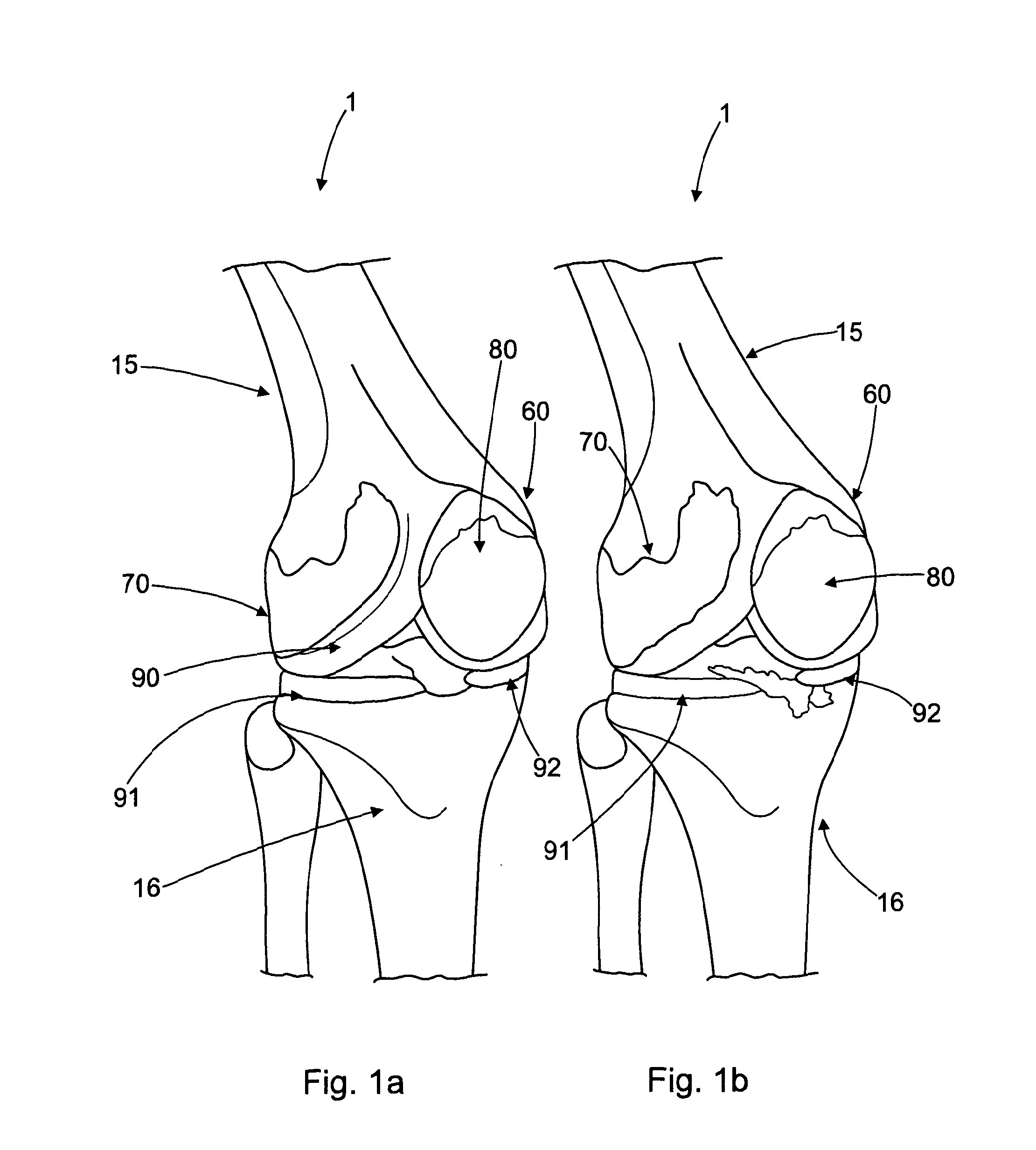
[0090]FIG. 1a shows a healthy knee joint 1 and FIG. 1b shows a knee joint showing progressive knee joint degeneration. The knee joint 1 is where the end of the femur 15 meets the top of the tibia 16. The end of the femur 15 consists of two condyles 60, 70. These condyles 60, 70 sit on top of the tibia 16, which is like a platform. Thus, on each side of the joint 1, there is an area of contact between the two bones. When the knee is bent, the condyles 60, 70 of the femur 15 roll and slide on top of the tibia 16 at these two areas of contact. A third bone, the kneecap (patella) 80, glides over the front and end of the femur 15.

[0091]In a healthy knee joint (FIG. 1a), the surfaces of these bones are very smooth and covered with cartilage—a tough protective tissue. The articular disks of the knee-joint are called menisci 91, 92 because they only partly divide the joint space. These two disks, the medial meniscus 91 and the lateral meniscus 92, consist of connective tissue with extensive...


PUM


Abstract

The invention concerns a tibial prosthetic component comprising a plate (100) for forming a tibial plateau of a tibia (16), wherein a peripheral region of the plate (100) has a thickness of less than 3 mm. The invention also concerns a tibial prosthetic component having a keel of depth less than 9 mm. The invention also concerns a method of selecting a tibial prosthetic component comprising receiving measurements of at least one physical attribute of an individual into whom the tibial prosthetic component is to be implanted, selecting a thickness of a plate (100) and depth of keel of the tibial prosthetic component based on the measurements and providing a tibial prosthetic component comprising a plate (100) having the selected thickness and a keel having the selected depth. The invention may also comprise implanting a tibial prosthetic component selected in accordance with this method into an individual and a kit comprising a plurality of prosthetic components comprising plates having different thicknesses with keels of different depths.

Description

CROSS-REFERENCE TO RELATED APPLICATION(S)[0001]The present application claims priority under 35 U.S.C. §365 to International Patent Application No. PCT / GB2011 / 050486 filed Mar. 11, 2011. International Patent Application No. PCT / GB2011 / 050486 claims priority under 35 U.S.C. §365 and / or 35 U.S.C. §119(a) to United Kingdom Patent Application No. 1004068.1 filed Mar. 11, 2010 and which are incorporated herein by reference into the present disclosure as if fully set forth herein.FIELD OF THE INVENTION[0002]This invention concerns a tibial prosthetic component for a partial or unicondylar bearing knee replacement, and in particular a partial or unicondylar meniscal bearing knee replacement, a method of selecting such a tibial prosthetic component, a method of implanting such a tibial prosthetic component during knee surgery, and a kit for surgeons.[0003]The knee comprises three inter-dependent joints in three separate compartments, all surrounded by a fibrous capsule covered by the skin. ...

Claims


Application Information

Patent Timeline
Patent Type & Authority Applications(United States)
IPC IPC(8): A61F2/38
CPCA61F2/389A61F2/4684A61F2002/30168A61F2002/30594A61F2002/3895A61F2002/30878A61F2002/30884A61F2002/30901A61F2002/30616A61F2/28A61F2/30A61F2/38
Inventor GOODFELLOW, JOHNO'CONNOR, JOHNDODD, CHRISMURRAY, DAVID
Owner OCONNOR JOHN
Why Eureka
Try Eureka