
Method for treating elongate metal tension member with volatile corrosion inhibitors

a technology of elongate metal tension member and volatile corrosion inhibitor, which is applied in the direction of coatings, building components, structural elements, etc., can solve the problems of vci loss to the outside atmosphere, limited above-mentioned approaches, and the extent of corrosion protection tends to diminish, so as to achieve simple and low cost, enhanced corrosion protection

Active Publication Date: 2016-09-06
CORTEC CORP
View PDF33 Cites 12 Cited by
  • Summary
  • Abstract
  • Description
  • Claims
  • Application Information

AI Technical Summary

Benefits of technology

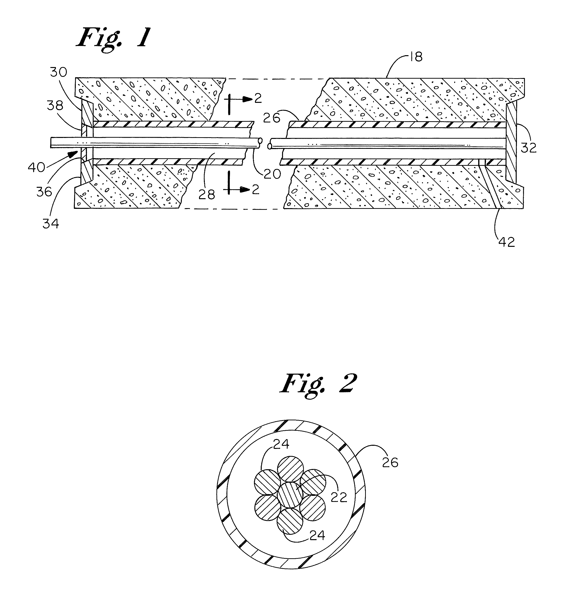
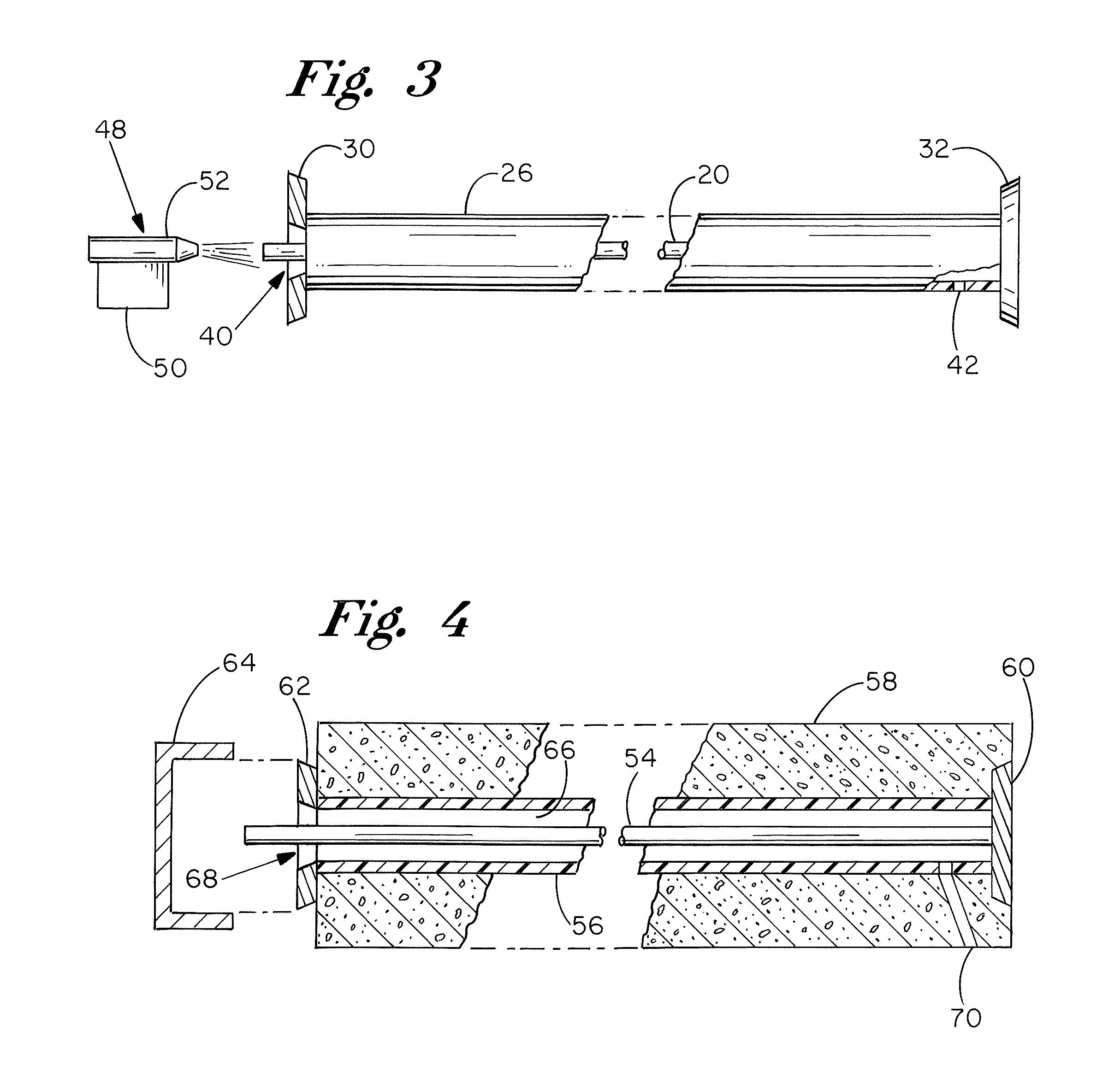
The patent describes a method for protecting metal components from corrosion in structures, such as cables and tension members. The method involves using a volatile corrosion inhibiting agent (VCI) that is solid or liquid at room temperature, but has a vapor phase at equilibrium. The VCI agent is placed in an enclosed space and a carrier gas is passed through it, creating a vapor stream with the VCI agent. This vapor stream is then used to distribute the corrosion inhibitor throughout the interior of the structure, providing continuous protection against corrosion. The method is simple and cost-effective, and can be used both during installation and inspection of the tension members.

Problems solved by technology

However, experience has shown that there are limits to the above approach.
In non-closed systems, the VCI can be lost to the outside atmosphere.
Even in closed systems, the extent of corrosion protection tends to diminish at distances more than several feet from the VCI material packet.
This is particularly problematic in enclosures with a high aspect ratio (e.g. inside a pipe).
A persistent problem with elongate metal tension members is corrosion of the metal, particularly in environments involving exposure to salts and other environmental treatment materials (e.g. de-icing chemicals), acid rain, airborne salts in locations near the ocean, and high humidity.
If undetected or untreated, corrosion can weaken metal tension members to the point of breakage.
In typical post-tensioned structures where the cables or other members are not bonded to the surrounding concrete, breakage of a tensioned member can create a risk of serious injury and property damage.
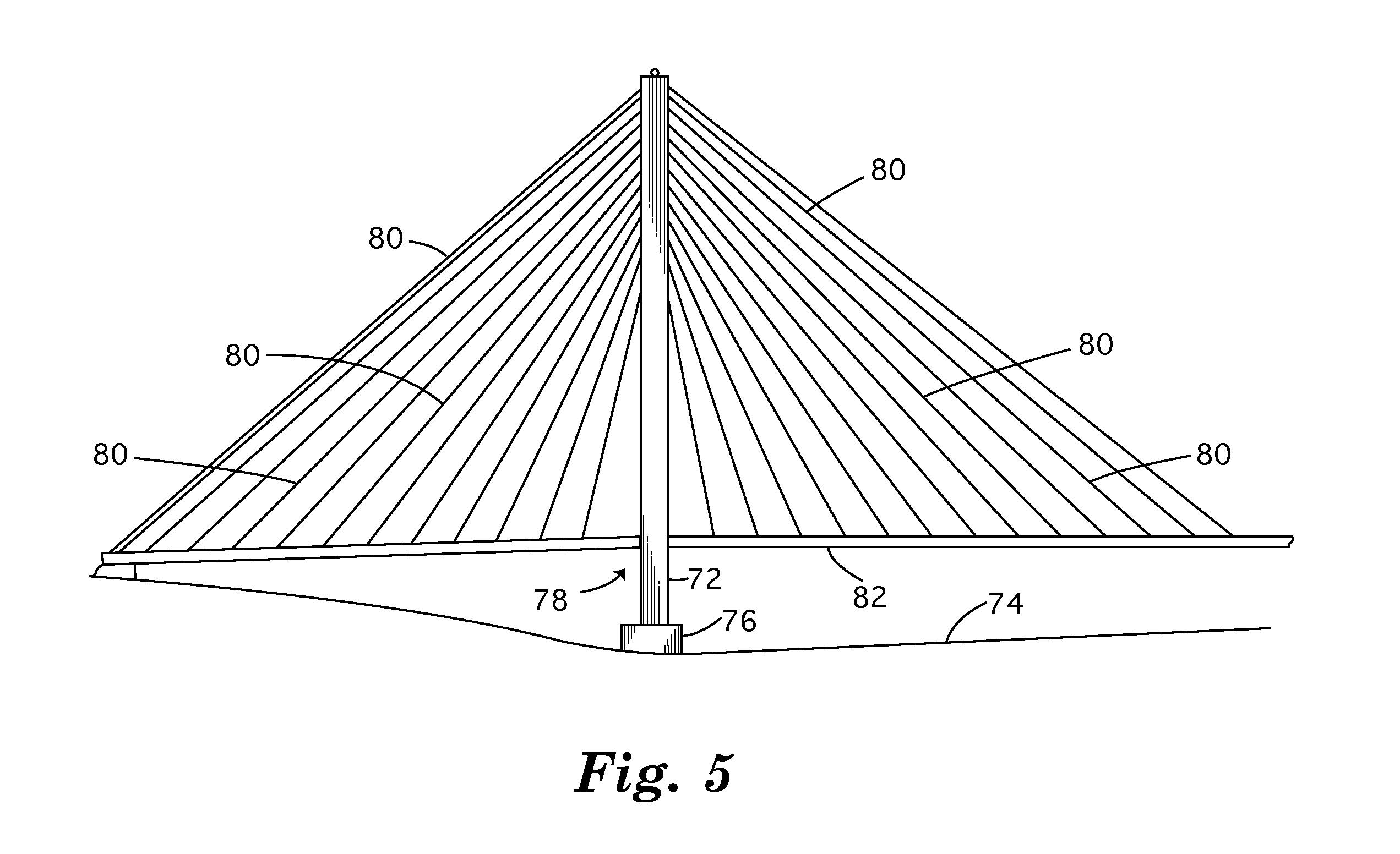
For cables and other tension members in a bridge, corrosion can weaken the integrity of the support systems leading to use restrictions, expensive repairs, premature bridge replacement, or catastrophic failure.
The patent notes that if the evaluation of the gas indicates a humidity above sixty percent, corrosion will ensue.
While the foregoing approaches are acceptable for a variety of applications, none of them is particularly well suited for providing corrosion protection for large scale systems in which the tension members may have considerable length, e.g. exceeding one hundred feet.
Drilling holes for injecting anti-corrosive grout or oil becomes prohibitively expensive and time consuming, and corrosion of longer lengths of tensioned members is not adequately addressed by end caps or similarly restricted features.
Coating tension members directly with anti-corrosive layers or films inhibits corrosion, but is not a practical approach for treating previously installed systems.
However, these measures sometimes prove insufficient, and there is a need for cost effective post treatments to further inhibit corrosion.
While potentially effective at reducing or eliminating corrosion, the approach has some disadvantages.
First, the vertical distance from the top anchor to the bottom anchor can create significant head pressure at lower portions of the cable sheathing.
Any leaks in the sheathing can result in an unintended release of corrosion inhibitor liquid into the environment, as well as loss of corrosion protection in that cable assembly.
Further, on a large bridge, this may require the acquisition and handling of large quantities of corrosion inhibitor fluids.

Method used


Image

  • Method for treating elongate metal tension member with volatile corrosion inhibitors
  • Method for treating elongate metal tension member with volatile corrosion inhibitors
  • Method for treating elongate metal tension member with volatile corrosion inhibitors

Examples


example 1

[0058]

ConstituentPercent by WeightCyclohexylammonium Benzoate87Monoethanolammonium Benzoate10Amorphous Silica3

example 2

[0059]

ConstituentPercent by WeightCyclohexylammonium Benzoate60Monoethanolammonium Benzoate20Dicyclohexcyl Ammonium Nitrate20

example 3

[0060]

ConstituentPercent by WeightCyclohexylammonium Benzoate55Monethanolammonium Benzoate20Dicyclohexcyl Ammonium Nitrate20Benzotriazole5

[0061]It is advantageous that the inhibitor materials are supplied as dry powders. The powders are preferably enclosed in a porous bag or pouch, to facilitate easy handling. Different VCI agents typically have different equilibrium vapor pressures resulting in different rates of volitization at a given set of conditions. Thus, a blend of VCI agents may be advantageous in providing fast initial distribution of vapor phase corrosion inhibitor into the vapor stream as well as assuring ongoing VCI emissions. For example, more VCI enters the vapor phase in a given amount of time for a material with a “higher” equilibrium vapor pressure (e.g. >1×10⁻⁴ mm Hg), in comparison to a VCI with a “lower” equilibrium vapor pressure. The “higher” equilibrium vapor pressure VCI material is therefore deemed to provide “fast” volitization and corrosion protection. In...


PUM

PropertyMeasurementUnit
humidityaaaaaaaaaa
humidityaaaaaaaaaa
pressureaaaaaaaaaa

Abstract

A volatile corrosion inhibiting agent is provided for dispersion of a vapor phase corrosion inhibitor in a vapor stream that is passed into a sheath or other casing enclosing a metal bar, cable, or other tension member to protect said tension member from corrosion.

Description

CROSS-REFERENCE TO RELATED APPLICATIONS[0001]This application claims the filing benefit and priority of U.S. Non-Provisional application Ser. No. 12 / 871,004, filed on Aug. 30, 2010, now U.S. Pat. No. 8,800,224 B2, and U.S. Non-Provisional application Ser. No. 11 / 559,482, filed on Nov. 14, 2006, now U.S. Pat. No. 7,892,601 B2, the contents of which are incorporated herein in their entireties.BACKGROUND OF THE INVENTION[0002]The present invention relates to vapor phase corrosion inhibiting compositions, and more particularly to inhibitors specifically formulated to provide corrosion protection of metal in recessed areas or encased, e.g. cables inside tubes.[0003]Vapor phase corrosion inhibiting (VCI) materials are utilized in a variety of applications for protecting metal from corrosion, and generally include chemicals which function as corrosion inhibitors and which are primarily in the solid or liquid state at ambient temperatures, but which exhibit a small but significant vapor pre...

Claims


Application Information

Patent Timeline
Patent Type & Authority Patents(United States)
IPC IPC(8): C23F11/02B05D7/14B05D1/06E04C5/01
CPCC23F11/02B05D1/06B05D7/14E04C5/015B05D2202/00
Inventor KHARSHAN, MARGARITAFURMAN, ALLAJACKSON MEYER, JESSI
Owner CORTEC CORP
Learn More