Rotary input device

a rotary input and input device technology, applied in the direction of mechanical control devices, instruments, pulse techniques, etc., can solve the problems of increasing the cost according to the magnetization and not being able to achieve an improved click feeling

Active Publication Date: 2016-09-06
ALPS ALPINE CO LTD
View PDF14 Cites 60 Cited by
  • Summary
  • Abstract
  • Description
  • Claims
  • Application Information

AI Technical Summary

Benefits of technology

[0013]The present invention provides a rotary input device capable of decreasing a cost required for a structure to obtain a click feeling and obtaining an improved click feeling.
[0015]According to this configuration, the upper surface and the lower surface of the magnet magnetized to two poles vertically are interposed by the yokes, the outward protrusions or the inward protrusions are formed on the yokes, and thus, it is possible to effectively transmit the magnetic flux of the magnet to opposing magnetic bodies. Therefore, the magnetic attraction is increased, and it is possible to improve the click feeling generated when the rotary knob is operated by the change of the magnetic attraction. Since the magnet is vertically magnetized, a simple structure is obtained even when the magnet is an annular shape, and the manufacturing of the magnet is easy. Accordingly, it is possible to provide the rotary input device in which the cost can be decreased and the click feeling is improved.
[0017]According to this configuration, since the cam member applies the operation reaction force to the rotary knob, it is possible to prevent the rotary knob from not being stopped and being continuously vibrated, and it is possible to limit the continuous rotation. Moreover, since the click feeling is generated by the change of the magnetic attraction, it is possible to decrease the operation reaction force generated in the cam member. Accordingly, since the friction force or the like applied to the cam member is decreased, wear is decreased and the lifespan can be lengthened.
[0019]According to this configuration, since the cam member can be configured by a simple structure, it is possible to decrease the cost. In addition, since the click feeling is generated by the change of the magnetic attraction, it is possible to decrease the elastic force of the elastic member generating the operation reaction force, and thus, the operation sound or the wear due to the sliding is not easily generated.
[0021]According to this configuration, the first magnetic body and the second magnetic body respectively include the magnets, the magnets are disposed to attract each other, and thus, it is possible to further increase the magnetic attraction.
[0023]According to this configuration, the magnet is an electromagnet, and since it is possible to control the magnetic attraction by energizing the coil material, it is possible to freely change the operation feeling.

Problems solved by technology

Therefore, there is a problem that a cost according to the magnetization is increased.
Moreover, when magnetic attraction is not strong, it is not possible to obtain an improved click feeling.

Method used


Image

  • Rotary input device
  • Rotary input device
  • Rotary input device

Examples


first embodiment

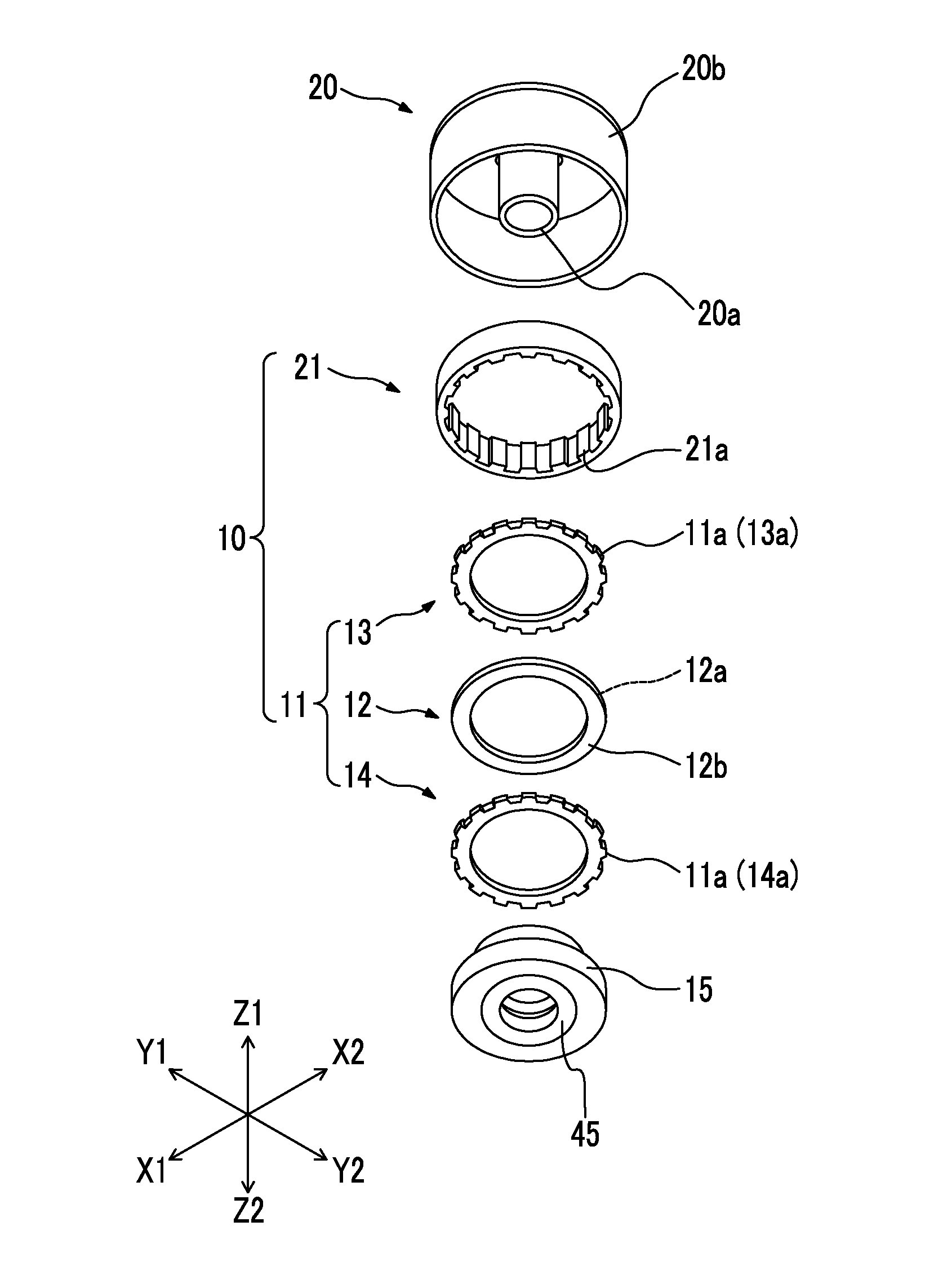
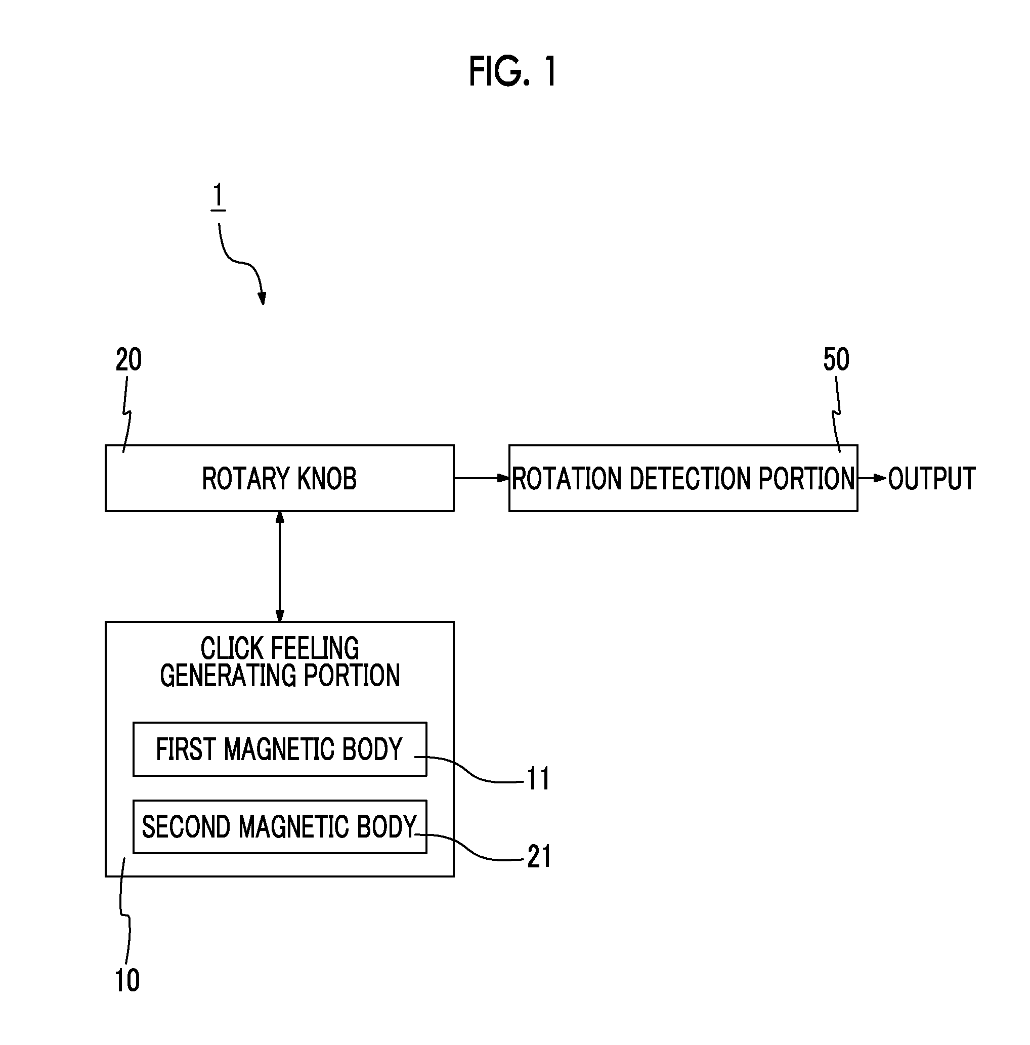
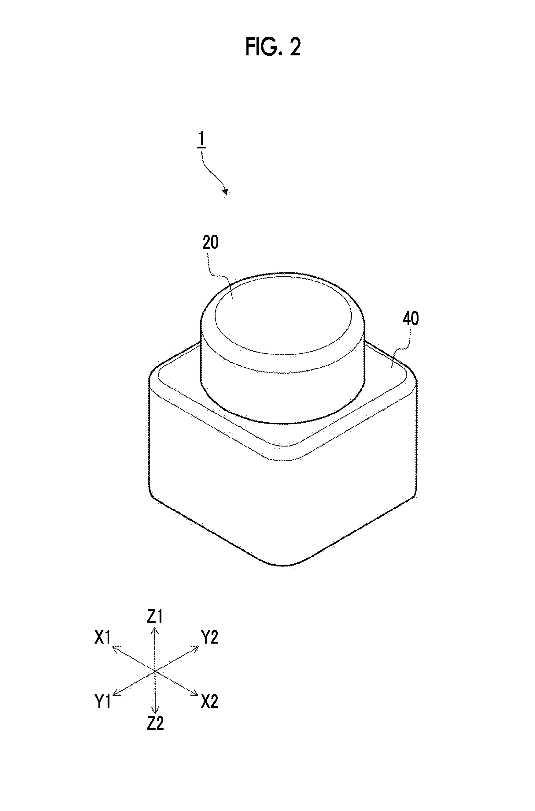
[0050]FIG. 1 is a block diagram showing a rotary input device 1 of a first embodiment of the present invention. FIG. 2 is a perspective view showing the rotary input device 1 of the first embodiment. FIG. 3 is an exploded perspective view showing a rotary knob 20 and a click feeling generating portion 10 in the rotary input device 1 of the first embodiment. FIG. 4 is a front view showing the rotary input device 1 of the first embodiment. FIG. 5 is a cross-sectional view taken along line V-V of FIG. 4. FIG. 6 is a cross-sectional view taken along line VI-VI of FIG. 4.

[0051]The rotary input device 1 of the present embodiment is a mechanism by which an operator performing a rotation input operation of the rotary knob 20 obtains a click feeling. More specifically, the rotary input device is used for an input operation mechanism used in an input operation of electronic equipment or a vehicle. For example, different operation contents are input according to a rotation angle from a predete...

second embodiment

[0075]FIG. 13 is an exploded perspective view showing a rotary knob 30 and the click feeling generating portion 10 in a rotary input device 2 of a second embodiment. FIG. 14 is a cross-sectional view of the rotary input device 2 which is cut similar to that in FIG. 5.

[0076]In the rotary input device 2 of the second embodiment, the rotary knob 30 and a case member 41 are different from those of the rotary input device 1 of the first embodiment. Other members are the same as in the first embodiment, and thus, the same reference numerals are used, and the descriptions thereof are omitted.

[0077]The rotary knob 30 is a molding member that includes a cylindrical operating portion 30b, and a shaft portion 30a that is concentrically formed with the operating portion 30b. The rotary knob 30 is accommodated in the case member 41 that rotatably supports the rotary knob 30, and the operating portion 30b protrudes from an opening of the case member 41.

[0078]As shown in FIG. 13, in the rotary inp...

third embodiment

[0083]FIG. 15 is a cross-sectional view showing a rotary input device 3 of a third embodiment. FIG. 16 is an explanatory view showing flows of the magnetic flux of a first magnetic body and a second magnetic body in a B portion of FIG. 15.

[0084]In the rotary input device 3 of the third embodiment, a second magnetic body 61 is different from that of the rotary input device 1 of the first embodiment. Other members are the same as in the first embodiment, and thus, the same reference numerals are used, and the descriptions thereof are omitted.

[0085]As shown in FIG. 15, the rotary input device 3 of the third embodiment includes the second magnetic body 61, a magnet 62, and a pair of yokes 63 and 64. The second magnetic body 61 is positioned vertically (Z1-Z2 direction) by a fixing member 25, and is inserted to be fixed to the operating portion 20b of the rotary knob 20.

[0086]As shown in FIG. 16, in the rotary input device 3 of the present embodiment, the first magnetic body 11 includes ...


PUM

PropertyMeasurementUnit
magneticaaaaaaaaaa
elastic forceaaaaaaaaaa
circumferenceaaaaaaaaaa

Abstract

A rotary input device includes a first annular magnetic body in which a plurality of outward protrusions protruding toward an outside in a radial direction are disposed along a circumferential direction, a second annular magnetic body in which a plurality of inward protrusions formed to oppose the outward protrusions of the first magnetic body are disposed along a circumferential direction, and a rotary knob configured to relatively rotate the first magnetic body and the second magnetic body. The first magnetic body includes a magnet in which opposing surfaces facing each other are vertically disposed and which is magnetized to two poles of an upper pole and a lower pole including the opposing surfaces, a pair of yokes that interposes the opposing surfaces of the magnet vertically, and the outward protrusion formed on the pair of yokes.

Description

CLAIM OF PRIORITY[0001]This application claims benefit of Japanese Patent Application No. 2014-016542 filed on Jan. 31, 2014, which is hereby incorporated by reference.BACKGROUND OF THE INVENTION[0002]1. Field of the Invention[0003]The present invention relates to a rotary input device by which a click feeling can be obtained.[0004]2. Description of the Related Art[0005]In recent years, a rotary input device by which a click feeling can be obtained is used in various industrial fields. For example, an information input device for rotation detection is disclosed in Japanese Unexamined Patent Application Publication No. 2003-280799.[0006]FIG. 24 is an exploded perspective view showing an information input device 100 disclosed in Japanese Unexamined Patent Application Publication No. 2003-280799. FIGS. 25A and 25B are perspective views showing a rotation detection magnetic body 152 of FIG. 24, FIG. 25A is a perspective view showing a positional relationship of a hall IC 136a with respe...

Claims


Application Information

Patent Timeline
Patent Type & Authority Patents(United States)
IPC IPC(8): H01H9/00H01F7/02G05G1/08G05G5/03H01H5/02G06F3/0362G01B7/00G01B7/30H01F7/20H03K17/97H01H19/11H01H3/50H01H25/06
CPCH01F7/021G01B7/003G01B7/30G05G1/08G05G5/03G06F3/0362H01F7/20H01H5/02H01H19/11H03K17/97G01B2210/58H01H25/06H01H2003/506H03K2217/94068H03K2217/96062G05G5/06G05G9/047
Inventor FURUKI, SHIGERUHAYASHI, YUKIHARUHASHIRA, HIROSHIIWAZAKI, YOSHIYUKI
Owner ALPS ALPINE CO LTD
Why Eureka
Try Eureka