Drill stem component comprising a movable coupler and a pressure chamber

Active Publication Date: 2016-09-13
BAKER HUGHES INC
View PDF9 Cites 0 Cited by
  • Summary
  • Abstract
  • Description
  • Claims
  • Application Information

AI Technical Summary

Benefits of technology

[0022]Displacement of the coupler is thus minimized by maintaining an equal pressure of the spaces located axially to either side of the coupler. The force to be applied to retain contact is minimized.
[0023]The device and the mounti

Problems solved by technology

Known contact transmissions are subject to wear and cannot guarantee sufficient service use.
The

Method used


Image

  • Drill stem component comprising a movable coupler and a pressure chamber
  • Drill stem component comprising a movable coupler and a pressure chamber
  • Drill stem component comprising a movable coupler and a pressure chamber

Examples


Example

[0042]The accompanying drawings are at least partially specific in nature and may not only serve to complete the invention, but also to contribute to the definition if necessary.

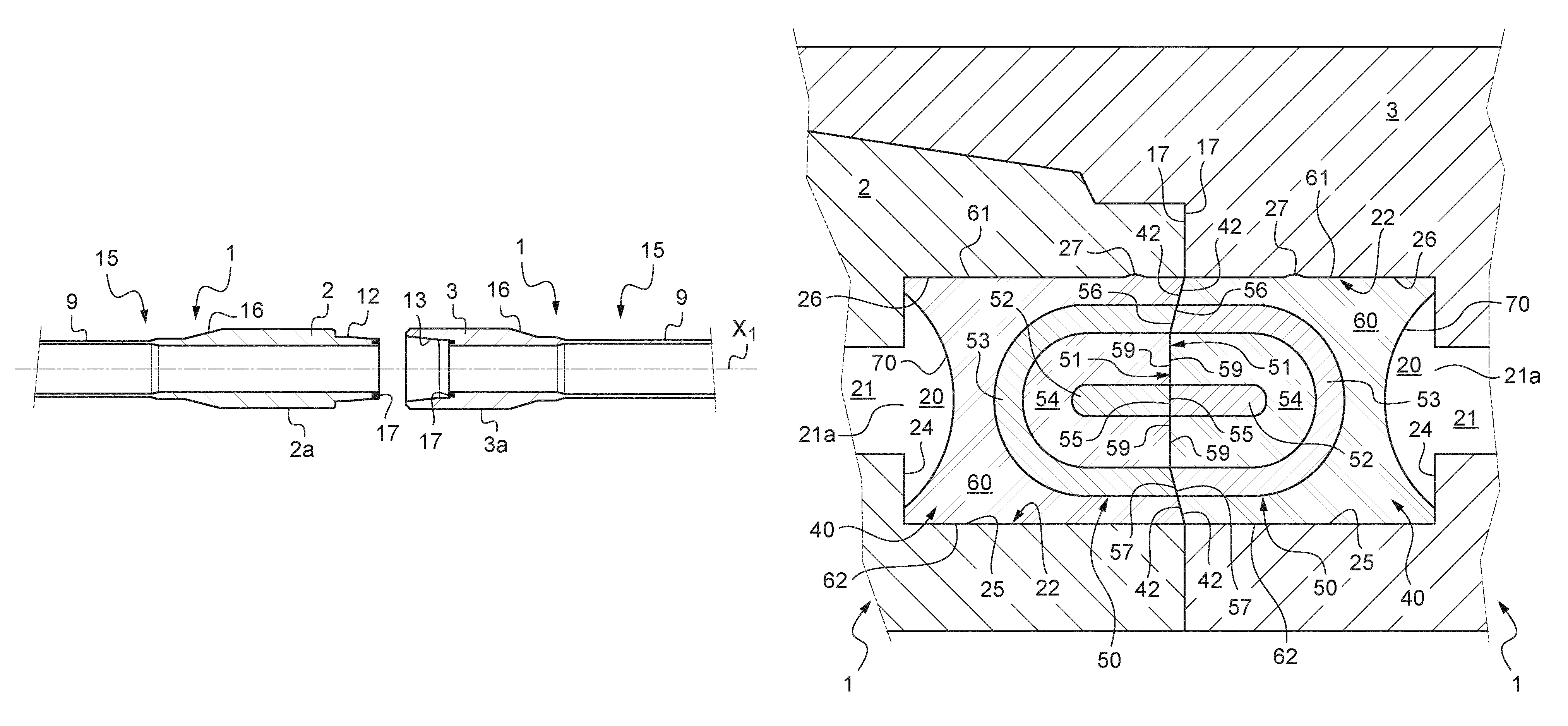
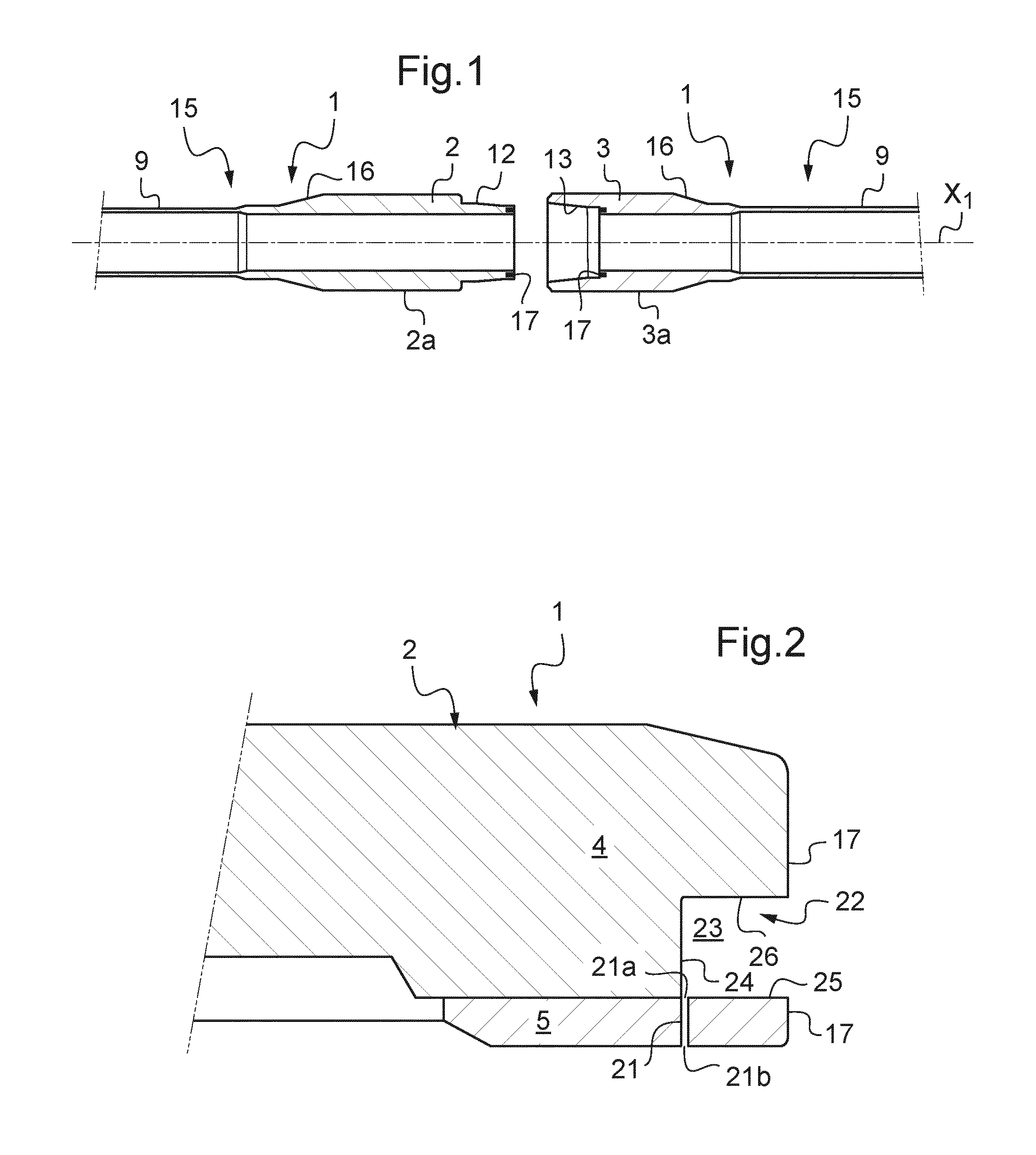
[0043]A drill stem may comprise a plurality of pipes, especially standard pipes obtained by coupling, by welding, a first connector (or male / female end zone) of a great length tube and a second connector (or female / male end zone) on the side opposite to the first connector to form leak-proof threaded tubular connections by coupling, and possibly heavy weight pipes. A pipe may be of any type from several that comply with specification API 7 from the American Petroleum Institute or the manufacturer's own designs. The drill string may be of the type described in documents U.S. Pat. No. 6,670,880, U.S. Pat. No. 6,717,501, US 2005 / 0115717, US 2005 / 0092499, US 2006 / 0225926, FR 2 883 915, FR 2 936 554 or FR 2 940 816.

[0044]The term “substantially” as used below takes into account the usual tolerances in the technic...


PUM


Abstract

A rotary drill stem for a well including a central tubular element, and first and second connectors each including a threaded portion that can connect the element to another element. At least one of the connectors includes a chamber in communication with a pressure outside the chamber. The connector includes an annular signal transmission coupler. The annular coupler includes a ring having an annular coupling surface. The coupler includes an insulating support that leaves the annular coupling surface free. The coupler includes a piston surface axially opposite to the annular coupling surface. The annular coupler forms a piston.

Description

FIELD OF THE INVENTION[0001]The invention relates to the field of the search for and working oil or gas fields. Rotary drill strings are used therein, constituted by tubular components such as standard drill strings and possibly heavy weight drill strings as well as other tubulars. The expression “drill string” will be used here, even if only one tube is involved, to denote the passage for mud under pressure in order to actuate a drill bit at the well bottom. The drill string may be rotary with respect to the casing of the well.[0002]More particularly, the invention pertains to a cabled tubular component provided with a coupler. Such couplers can transmit information from one end of a component to the end of another component.BACKGROUND OF THE INVENTION[0003]In order to provide a better understanding of the events occurring at the bottom of a hole, downhole assemblies in the vicinity of the bit may be provided with measuring instruments. The measured data are communicated to the sur...

Claims


Application Information

Patent Timeline
IPC IPC(8): E21B17/02E21B17/042E21B3/00
CPCE21B3/00E21B17/028E21B17/042E21B17/0285
Inventor MITJANS, BERANGERBUCHOUD, VINCENTMESNIL, PIERRE
Owner BAKER HUGHES INC
Why Eureka
Try Eureka