Apparatus and method for maintaining optical ferrule alignment during thermal expansion or contraction

Active Publication Date: 2021-08-12
3M INNOVATIVE PROPERTIES CO
View PDF0 Cites 2 Cited by
  • Summary
  • Abstract
  • Description
  • Claims
  • Application Information

AI Technical Summary

Benefits of technology

[0022]In some configurations, the two or more mounting members may comprise two or more legs affixed near a top surface of the cradle that is opposed to the two more bonding pads. The two or more legs may comprise four or more legs each affixed at a different corner of the cradle. The two or more legs may comprise three or more legs each affixed at a different edge of the cradle. The two or more mounting members may comprise two or more hollow cylinders or hollow prisms that extend away from a bottom surface of the cradle that faces the substrate. The two

Problems solved by technology

One challenge in utilizing a PIC in this way is efficient coupling of light between optical fibers and small-core PIC waveguides or other small-scale optical device

Method used


Image

  • Apparatus and method for maintaining optical ferrule alignment during thermal expansion or contraction
  • Apparatus and method for maintaining optical ferrule alignment during thermal expansion or contraction
  • Apparatus and method for maintaining optical ferrule alignment during thermal expansion or contraction

Examples


Example

[0041]The figures are not necessarily to scale. Like numbers used in the figures refer to like components. However, it will be understood that the use of a number to refer to a component in a given figure is not intended to limit the component in another figure labeled with the same number.

DETAILED DESCRIPTION OF ILLUSTRATIVE EMBODIMENTS

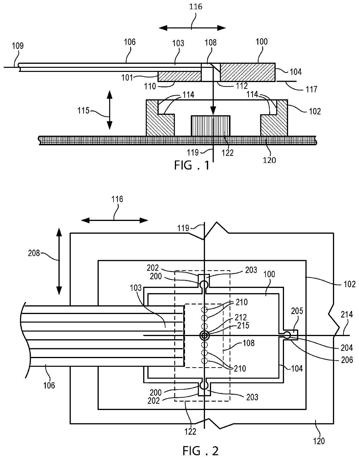
[0042]Embodiments described herein relate to optical cable subassemblies, optical connectors, and packages for photonic integrated circuits (PICs). Connector interfaces are described that can mate one or more fiber optic waveguides to corresponding optical devices that are mounted on or integral with a substrate. In some cases, the optical device and substrate may be formed integrally as part of a PIC. In other cases, the optical device may be mounted (e.g., bonded, soldered) to a circuit board, such that the circuit board acts as a substrate. In other cases, the optical device may be mounted on an interposer or other carrier, that is in turn mounted...


PUM


Abstract

An optical ferrule has a different thermal expansion coefficient than a substrate to which a optical device is mounted, the ferrule optically coupling the device to one or more optical fibers. The optical ferrule includes and/or a cradle in which the ferrule is mounted include lateral and longitudinal engagement feature that ensure alignment with the optical device at an operating temperature, the ferrule expanding relative to the substrate when transitioning to the operating temperature.

Description

TECHNICAL FIELD[0001]This disclosure relates generally to connector assemblies and methods related to connector assemblies.BACKGROUND[0002]Optical connectors can be used for a variety of applications including telecommunications networks, local area networks, data center links, and internal links in computer devices. Increasingly, optical functions are being incorporated in small integrated devices, such as photonic integrated circuits (PIC). A PIC device may include optical elements such as waveguides, gratings detectors, lasers, etc., that are fabricated using processes such as material deposition, photolithography, and etching. A PIC may be coupled with external optical devices via optical fibers. One challenge in utilizing a PIC in this way is efficient coupling of light between optical fibers and small-core PIC waveguides or other small-scale optical device on the PIC. Existing solutions involve active alignment of the fibers followed by permanent attachment to the devices, whi...

Claims


Application Information

Patent Timeline
IPC IPC(8): G02B6/42
CPCG02B6/4226G02B6/424G02B6/4214G02B6/4249G02B6/4204G02B6/3826
Inventor HAASE, MICHAEL A.
Owner 3M INNOVATIVE PROPERTIES CO
Why Eureka
Try Eureka