
Electrical apparatus having a gas insulation containing a fluorinated compound

a technology of fluorinated compound and electric apparatus, which is applied in the direction of switchgear arrangement, high-tension/heavy-dress switch, air-break switch, etc., can solve the problem of increasing the gas pressure in the housing, and achieve the effect of increasing the gas pressure, improving the effectiveness of means, and limiting the loss of heat produced by heating means

Active Publication Date: 2016-09-27
SCHNEIDER ELECTRIC IND SAS
View PDF27 Cites 1 Cited by
  • Summary
  • Abstract
  • Description
  • Claims
  • Application Information

AI Technical Summary

Benefits of technology

The invention is about an electrical device that regulates the pressure of fluorinated gas while minimizing heat loss. The device uses a heating system to increase the gas pressure in the device, reducing heat loss and improving the efficiency of the gas regulation system. The heating system can be a resistor or a solenoid with a ferromagnetic core. The technical effects of this invention include improved gas regulation and reduced heat loss, making it more efficient and reliable.

Problems solved by technology

The heating of the liquid formed by condensation causes it to vaporize and thus increases the gas pressure in the housing.

Method used


Image

  • Electrical apparatus having a gas insulation containing a fluorinated compound
  • Electrical apparatus having a gas insulation containing a fluorinated compound
  • Electrical apparatus having a gas insulation containing a fluorinated compound

Examples


first embodiment

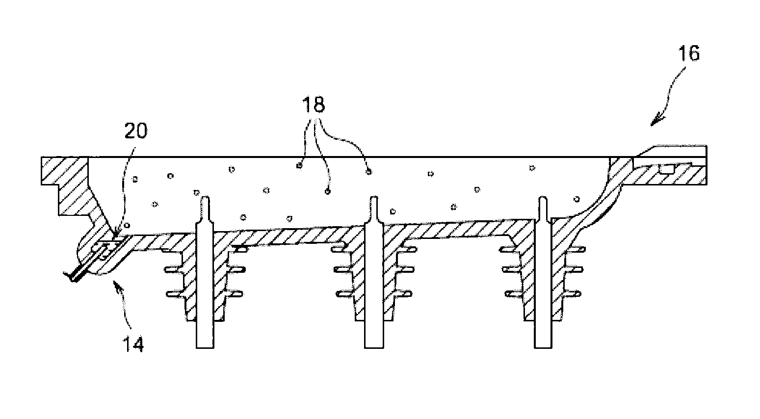
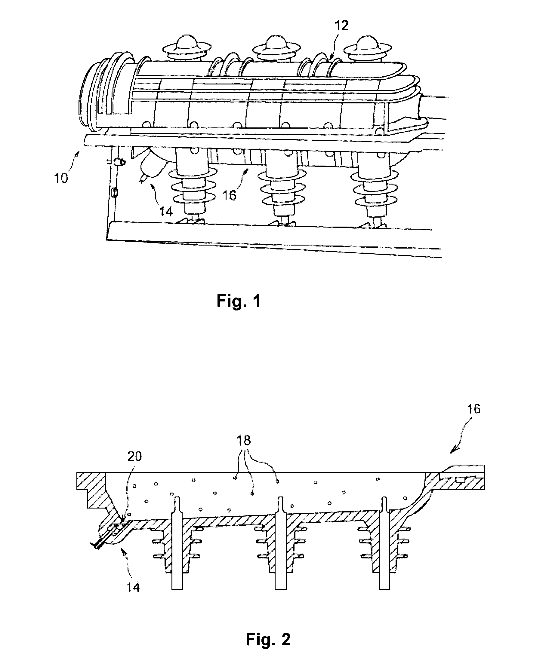
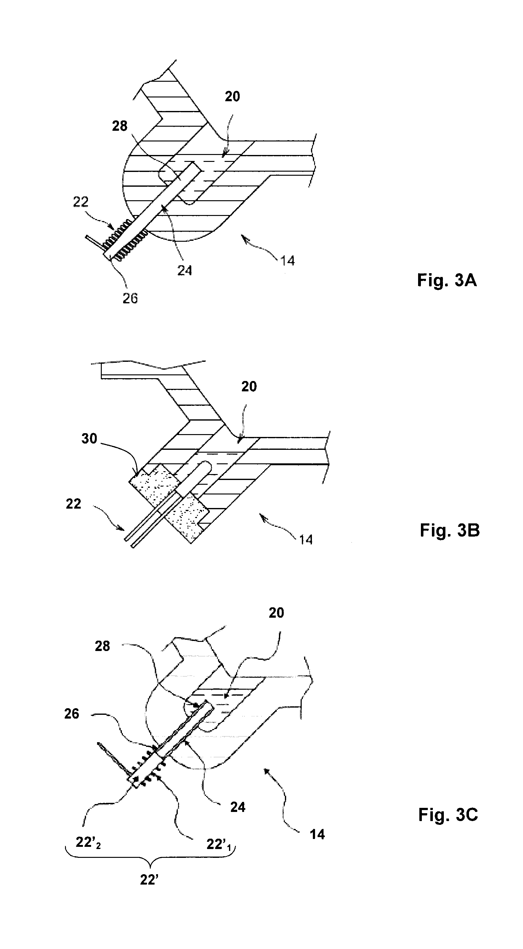
[0032]In a first embodiment illustrated in FIG. 3A, the heating means contain a resistor 22, for example an electrical resistor, which produces heat that is transmitted to the condensate; the heat produced by the resistor 22 is transmitted to the condensate by way of a heat conductor 24. This transmission of heat is particularly advantageous in the case where the housing 12 is made of thermally insulating material, because only the heat conductor 24 allows the heat produced by the resistor 22 to reach the condensate 20. It will nonetheless be understood that the heat conductor 24 may also be used for the embodiment in which the housing 12 is made from a thermally conductive material.

[0033]The resistor 22 is thus arranged outside the tank 14, preferably outside the housing 12, and the heat conductor 24 passes through the wall of the tank 14. A first end 26 of the heat conductor is located outside the housing 12 and is heated by the resistor, and a second end 28 of the heat conductor ...

second embodiment

[0036]In a second embodiment shown in FIG. 3C, the heating means 22′ comprise a solenoid 22′1 and its core 22′2. The heat produced is transmitted to the condensate 20, preferably by a way of a heat conductor 24, which may also be a filling tube: the solenoid 22′1 and its core 22′2 are thus arranged outside the tank 14, outside the housing 12, and the heat conductor 24 passes through the wall of the tank 14, a first end 26 of the heat conductor 24 being located outside the housing 12 and heated by the means 22′, and the second end 28 located inside the tank 14 heating the condensate 20. Thus, the heat produced by the solenoid and its core is transmitted to the condensate 20 by way of the heat conductor 24.

[0037]In another embodiment illustrated in FIG. 5, the tank 14 of condensate 20 contains a lower bottom wall 32 in which a cavity 34 is made. The cavity 34 protrudes vertically upwards with respect to the bottom wall 32: it therefore extends into the inside of the tank 14. The cavit...


PUM


Abstract

An electrical apparatus for a medium- to high-voltage current transport line having a gas insulation including: a sealed housing filled with an electrically insulating gas including at least one fluorinated compound such as a fluoroketone, at least one electrical component arranged inside the inner space of the housing, and a mechanism regulating an amount of the fluorinated compound inside the inner space of the housing. The regulating mechanism includes a heater, heating a liquid resulting from condensation of the fluorinated product present in the insulating gas, to cause at least a portion of the liquid to vaporize.

Description

TECHNICAL FIELD[0001]The invention relates to an electrical apparatus having a gas insulation for a medium- or high-voltage power transmission line, which contains means for regulating the quantity of insulating gas in suspension in the inner space of the insulating housing.PRIOR ART[0002]In an electrical apparatus for medium- or high-voltages, the functions of electrical insulation and electric arc extinction are typically performed by an insulating gas that is confined inside the apparatus. In the generally accepted sense of the term, “medium-voltage” denotes a voltage that is greater than 1,000 volts AC and strictly greater than 1,500 volts DC, but that does not exceed 52,000 volts AC or exceed 75,000 volts DC, whereas the term “high-voltage” denotes a voltage that is strictly greater than 52,000 volts AC and greater than 75,000 DC.[0003]According to one known embodiment, the insulating gas used inside these apparatuses contains sulphur hexafluoride SF6. Although it has very good...

Claims


Application Information

Patent Timeline
Patent Type & Authority Patents(United States)
IPC IPC(8): H02G7/05H02B13/055H01H33/56
CPCH02G7/05H02B13/055H01H2033/566
Inventor PICCOZ, DANIELMALADEN, ROMAIN
Owner SCHNEIDER ELECTRIC IND SAS
Learn More