Apparatus for eye tracking

a technology for eye tracking and eye tracking, applied in the field of eye tracking sensors, can solve the problems of limited field of view, general limitation of exit pupil of eye tracking trackers, and obscuration of vision and safety hazards, and achieve the effect of large field of view and high degree of transparency to external ligh

Active Publication Date: 2016-10-04
DIGILENS
View PDF28 Cites 98 Cited by
  • Summary
  • Abstract
  • Description
  • Claims
  • Application Information

AI Technical Summary

Benefits of technology

[0029]It is a first object of the invention to provide a compact, lightweight eye tracker with a large field of view, and a high degree of transparency to external light.
[0030]It is a second object of the invention to provide a compact, lightweight eye tracker with a large field of view, and a high degree of transparency to external light implemented in a thin optical waveguide.

Problems solved by technology

The exit pupil of these trackers is generally limited by either the size of the beamsplitter or the first lens of the imaging optics.
In order to maximize the exit pupil, the imaging optics are positioned close to the beamsplitter, and represent a vision obscuration and a safety hazard.
Another known limitation with eye trackers is the field of view, which is generally limited by the illumination scheme in combination with the geometry of the reflected images off the cornea.
The need for beam splitters and refractive lenses in conventional eye trackers results in a bulky component that is difficult to integrate into a (HMD).
The device exhibits near 100% efficiency with no voltage applied and essentially zero efficiency with a sufficiently high voltage applied.

Method used


Image

  • Apparatus for eye tracking
  • Apparatus for eye tracking
  • Apparatus for eye tracking

Examples


an embodiment

Using Separate Illumination and Detection Gratings

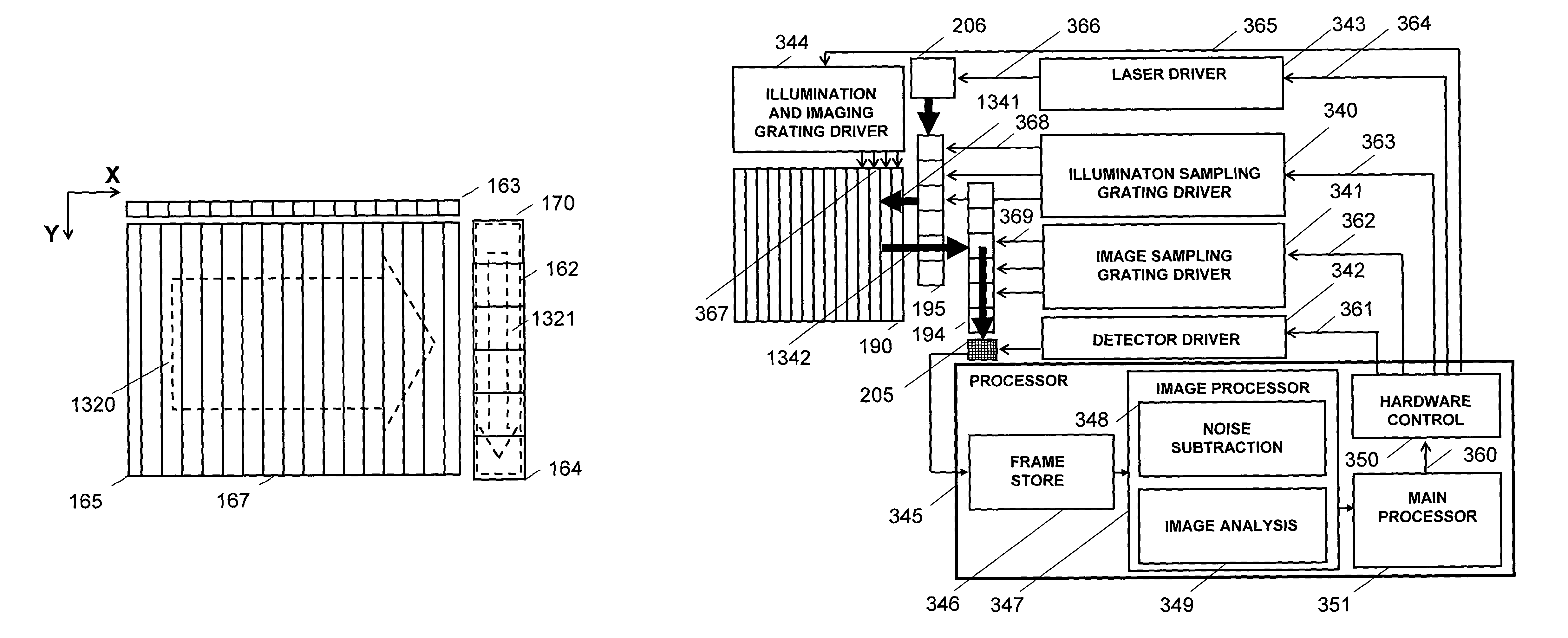
[0134]FIGS. 19-24 provide schematic illustrations of aspects of an eye tracker based on the principles of FIGS. 1-6. In this embodiment of the invention the earlier described imaging, illumination, input and output gratings are augmented by an additional grating to be referred to as an image sampling grating which overlays the output grating. FIG. 19 shows a side elevation view of the illumination grating 163. FIG. 20 is a plan view showing the imaging grating 165, the illumination grating 163 and the image sampling grating 170 overlaid on the output grating 164. FIG. 21 is a side elevation view of an alternative embodiment of the illumination grating 163. FIG. 22A is a plan view of the imaging grating, the image sampling grating 14 and the detector module 180. FIG. 22B is a plan view of the image sampling grating and the detector module. FIG. 22C is a cross sectional view showing the imaging grating and the image sampling grating. F...


PUM

PropertyMeasurementUnit
field of viewaaaaaaaaaa
sizeaaaaaaaaaa
wavelengthaaaaaaaaaa

Abstract

An eye tracker having a waveguide for propagating illumination light towards an eye and propagating image light reflected from at least one surface of an eye, a light source optically coupled to the waveguide, and a detector optically coupled to the waveguide. Disposed in the waveguide is at least one grating lamina for deflecting the illumination light towards the eye along a first waveguide path and deflecting the image light towards the detector along a second waveguide path.

Description

CROSS-REFERENCE TO RELATED APPLICATION[0001]This application is the U.S. national phase of PCT Application No. PCT / GB2013 / 000210 filed on May 10, 2013, which claims the benefit of U.S. Provisional Application No. 61 / 688,300 filed on May 11, 2012, the disclosures of which are incorporated in their entirety by reference herein.[0002]The following patent applications are incorporated by reference herein in their entireties:[0003]U.S. Provisional Patent Application No. 61 / 687,436 with filing date 25 Apr. 12 entitled WIDE ANGLE COLOUR HEAD MOUNTED DISPLAY.[0004]U.S. Provisional Patent Application No. 61 / 689,907 with filing date 25 Apr. 12 entitled HOLOGRAPHIC HEAD MOUNTED DISPLAY WITH IMPROVED IMAGE UNIFORMITY.[0005]U.S. Provisional Application No. 61 / 796,632 with filing date 16 Oct. 2012 entitled TRANSPARENT DISPLAYS BASED ON HOLOGRAPHIC SUBSTRATE GUIDED OPTICS.[0006]U.S. Provisional Application No. 61 / 849,853 with filing date 4 Feb. 2013 entitled TRANSPARENT WAVEGUIDE DISPLAY.[0007]PCT...

Claims


Application Information

Patent Timeline
Patent Type & Authority Patents(United States)
IPC IPC(8): A61B3/02F21V8/00G02F1/295G02B27/00G02B27/01A61B3/113G02B5/18G02B6/34G02F1/1334G02F1/29
CPCA61B3/113G02B6/0016G02B27/0093G02B27/017G02B27/0172G02F1/2955G02B5/18G02B6/34G02B2027/014G02B2027/0174G02B2027/0187G02F1/13342G02F2001/294G02F2201/16G02F2201/30G02F2201/307G02F2203/24G02F2203/28G02F2203/62G02F1/292G02F1/3132G02F1/294G06V40/193G02B6/4287G02B2027/0138G02F2201/302G02F2201/305H04N5/33
Inventor POPOVICH, MILAN MOMCILOWALDERN, JONATHAN DAVIDGRANT, ALASTAIR JOHN
Owner DIGILENS
Why Eureka
Try Eureka