Systems and methods for measuring parameters in joint replacement surgery

a technology for joint replacement and parameters, applied in the field of orthopedic surgery, can solve the problems of significant differences in the functionality of the patient's anatomy, significant differences in the patient's posture, gait, and/or range of motion, and the measurement is often inaccura

Active Publication Date: 2016-10-04
MAKO SURGICAL CORP
View PDF79 Cites 25 Cited by
  • Summary
  • Abstract
  • Description
  • Claims
  • Application Information

AI Technical Summary

Problems solved by technology

In some surgical procedures, particularly those involving orthopedic arthroplasty, relatively small deviations from a pre-operative plan can translate into significant differences in the functionality of the patient's anatomy.
For example, in joint replacement surgery on the knee or hip, small changes in the positioning of the prosthetic joint components may result in considerable differences in the patient's posture, gait, and / or range of motion.
Such measurements, however, are often inaccurate due to the difficulty in performing manual measurements in the surgical environment using conventional rulers and gauges.
Further, manual measurements are not easily repeatable or verifiable, and can take a significant amount of time to perform.
Indeed, if the surgeon fails to return the femur to the precise position and orientation, the hip parameters are subject to considerable error.
In some cases, this error may lead the surgeon to conclude that an improperly-aligned prosthetic is within an acceptable threshold of planned surgical goals, and end the surgery.
In other cases, an alignment error may lead the surgeon to conclude that a properly-aligned prosthetic deviates unacceptably from the threshold of planned surgical goals, causing the surgeon to make unnecessary adjustments to the position of the prosthetic implant(s) that may lead to a misalignment.
In either case, the patient may experience post-operative discomfort or, in the case of a severe misalignment, a dislocation of the prosthetic femoral head from the acetabular cup.
Such discomfort and / or dislocation may require corrective surgery, prolonged rehabilitation, and undue expense.

Method used


Image

  • Systems and methods for measuring parameters in joint replacement surgery
  • Systems and methods for measuring parameters in joint replacement surgery
  • Systems and methods for measuring parameters in joint replacement surgery

Examples


Embodiment Construction

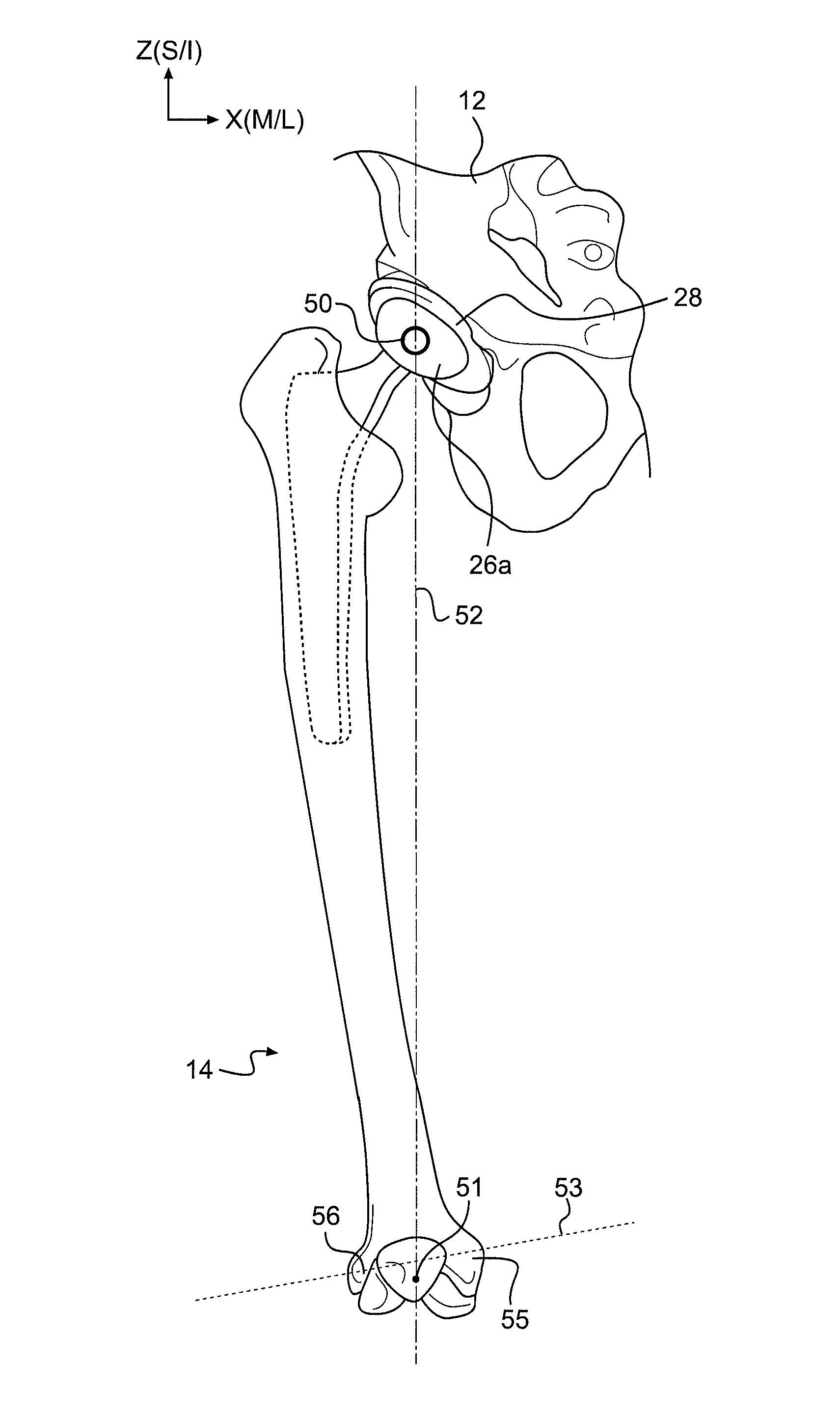
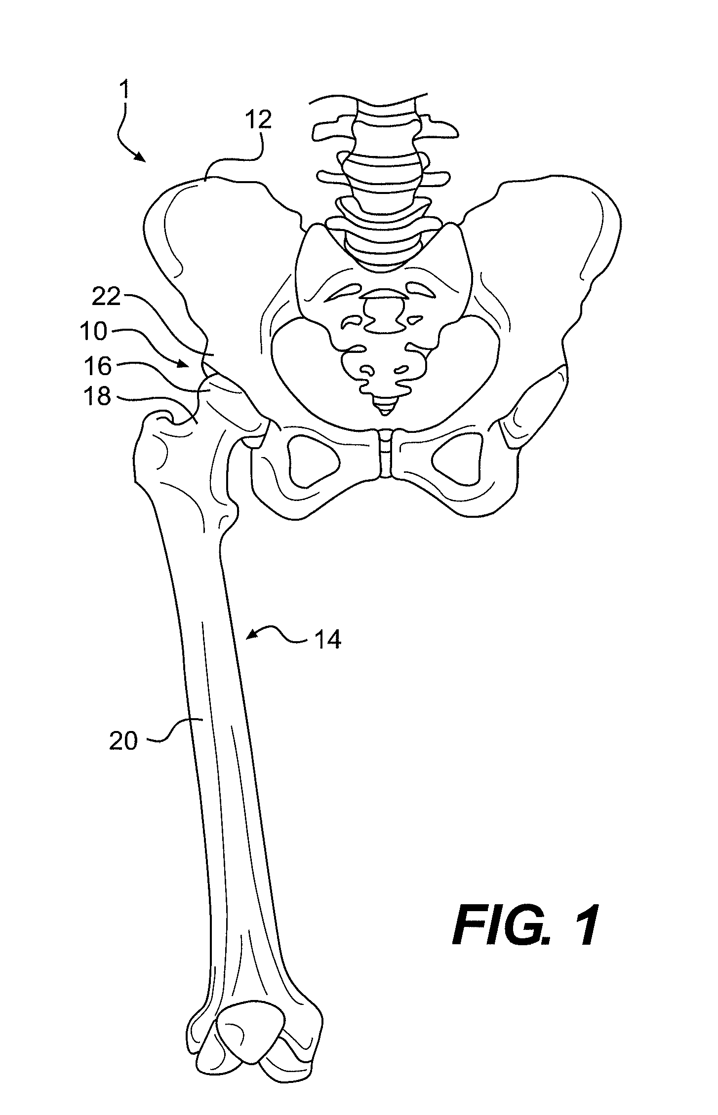
[0026]FIG. 1 illustrates a front view of an exemplary portion of the pelvic region 1 of the human body, which includes a hip joint 10. Proper articulation of hip joint 10 contributes to many basic structural and motor functions of the human body, such as standing and walking. As illustrated in FIG. 1, hip joint 10 comprises the interface between pelvis 12 and the proximal end of femur 14. The proximal end of femur 14 includes a femoral head 16 disposed on a femoral neck 18. Femoral neck 18 connects femoral head 16 to a femoral shaft 20. Femoral head 16 fits into a concave socket in pelvis 12 called the acetabulum 22. Acetabulum 22 and femoral head 16 are both covered by articular cartilage (not shown) that absorbs shock and promotes articulation of hip joint 10.

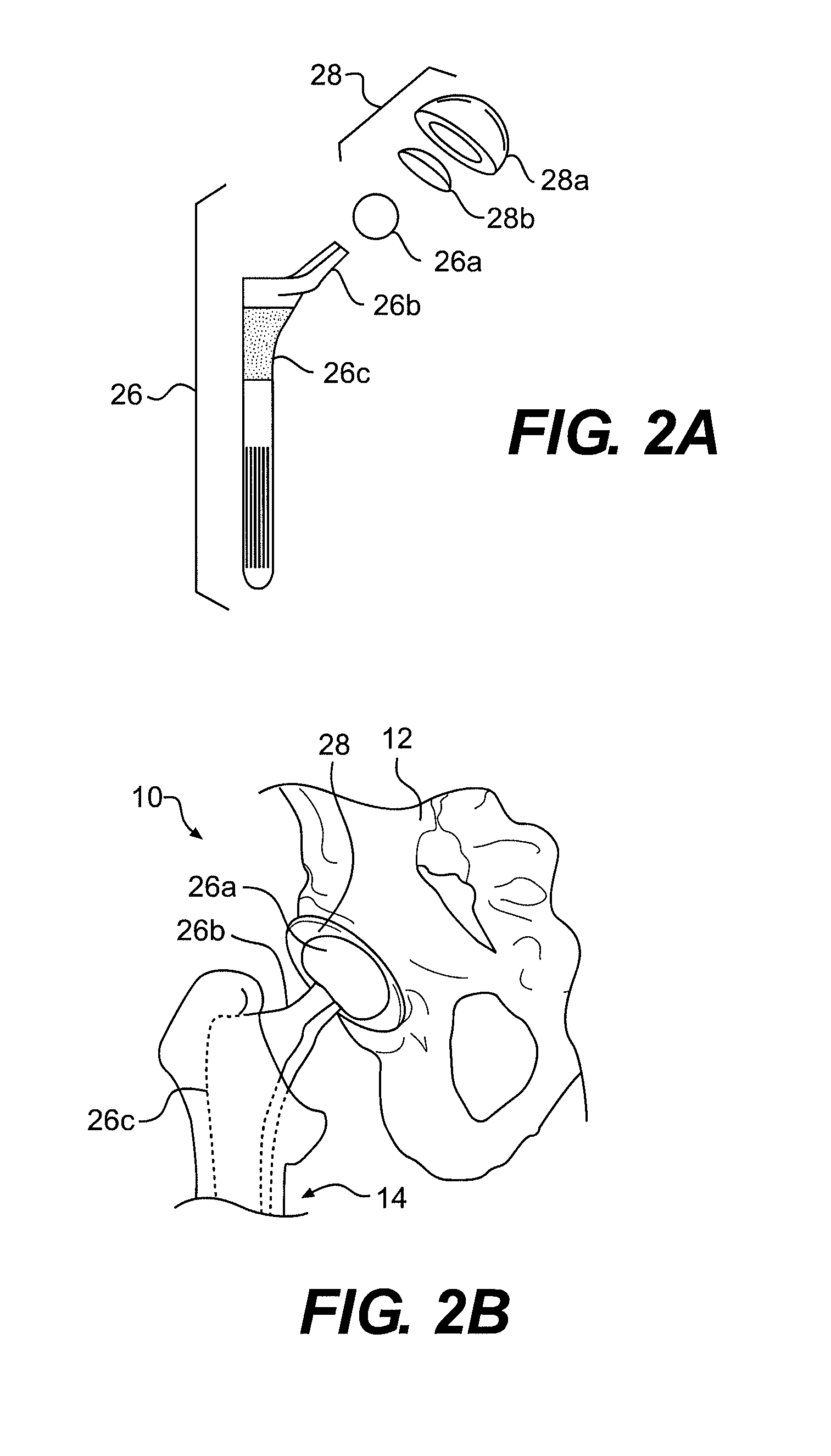
[0027]Over time, hip joint 10 may degenerate (due, for example, to osteoarthritis) resulting in pain and diminished functionality of the joint. As a result, a hip replacement procedure, such as total hip arthroplasty or hip r...


PUM


Abstract

A computer-assisted surgery system includes a display, an input device configured to receive data input by a user, and a processor, coupled to the input device and the display. The processor is configured to establish a first position of a pre-operative center of rotation of a joint in a first coordinate space of a first bone and a second coordinate space of a second bone and establish a second position of the pre-operative center of rotation of the joint in the first coordinate space, wherein the second position is a projection into the first coordinate space of the position of the pre-operative center of rotation maintained in a constant position in the second coordinate space. The processor is further configured to determine a change in a parameter associated with the joint based on the first and second positions and output a result indicating the determined change to the display.

Description

CROSS-REFERENCE TO RELATED APPLICATIONS[0001]This application is a divisional of U.S. application Ser. No. 13 / 234,190, filed Sep. 16, 2011, which is hereby incorporated by reference herein in its entirety.TECHNICAL FIELD[0002]The present disclosure relates generally to orthopedic surgery and, more particularly, to systems and methods for measuring parameters associated with joint replacement surgeries.BACKGROUND[0003]For most surgical procedures, it is advantageous for a surgeon to compare intra-operative progress and post-operative results with a pre-operative plan to ensure that surgical objectives are met. In some surgical procedures, particularly those involving orthopedic arthroplasty, relatively small deviations from a pre-operative plan can translate into significant differences in the functionality of the patient's anatomy. For example, in joint replacement surgery on the knee or hip, small changes in the positioning of the prosthetic joint components may result in considera...

Claims


Application Information

Patent Timeline
Patent Type & Authority Patents(United States)
IPC IPC(8): A61B5/00G06F19/00A61B5/107A61B5/06
CPCA61B5/06A61B5/107A61B5/4528A61B5/4571A61B5/4851A61B34/20G06F19/3437A61B2505/05A61B34/25A61B34/30A61B34/76A61B34/10A61B2034/107A61B90/37G16H50/50
Inventor ODERMATT, DANIELTHOMPSON, MATTHEW
Owner MAKO SURGICAL CORP
Why Eureka
Try Eureka