Supercharge Your Innovation With Domain-Expert AI Agents!

Rapid battery replacement and recharging techniques (CellGel)

a battery replacement and cell gel technology, applied in the field of electrochemical batteries, can solve the problems of difficult to meet the needs of secondary cells, difficult to recharge batteries, and relatively impractical power sources for high-power, high-capacity applications, etc., and achieve the effect of rapid exchang

Active Publication Date: 2016-10-04
BECKMAN CHRISTOPHER V
View PDF5 Cites 0 Cited by
  • Summary
  • Abstract
  • Description
  • Claims
  • Application Information

AI Technical Summary

Benefits of technology

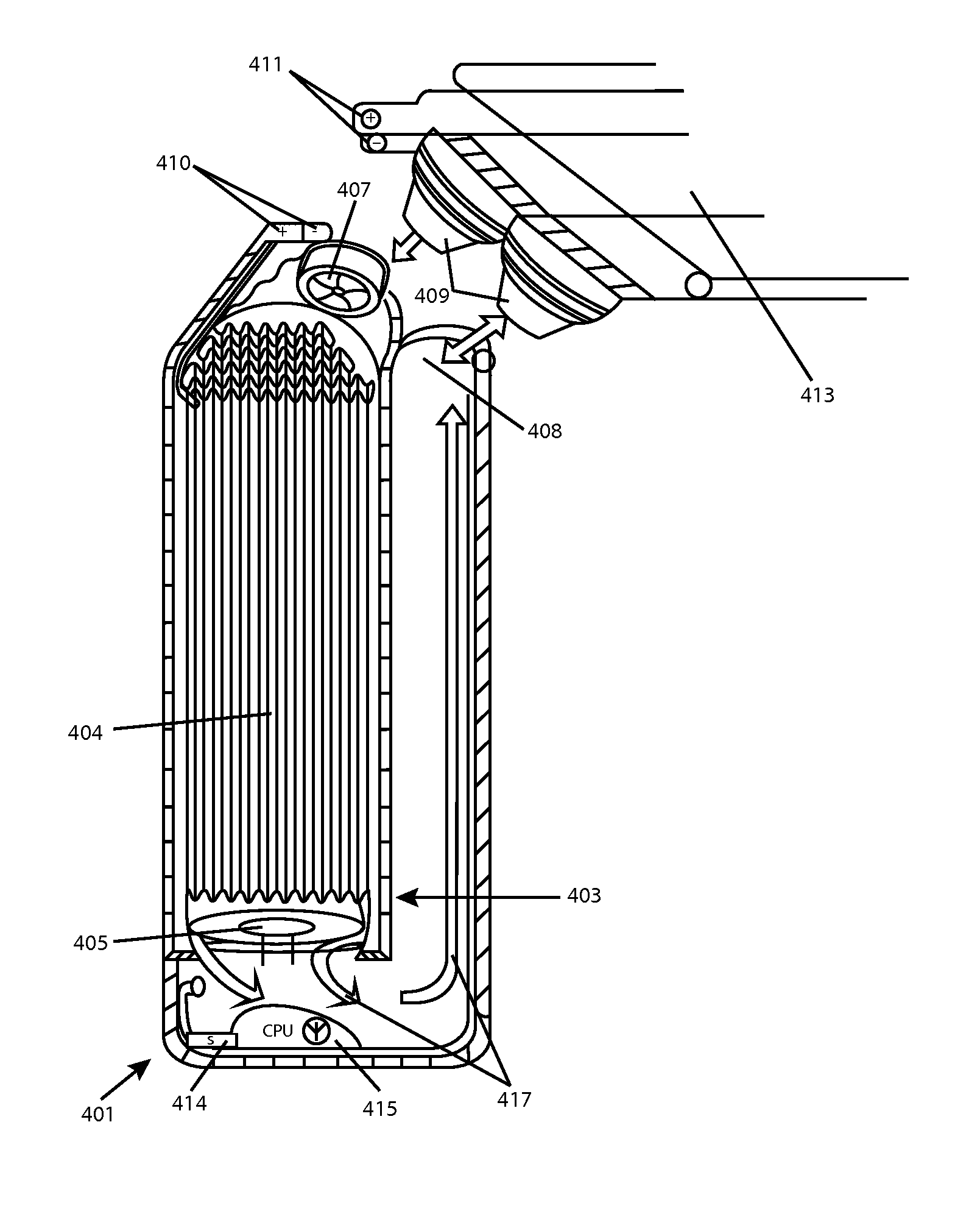
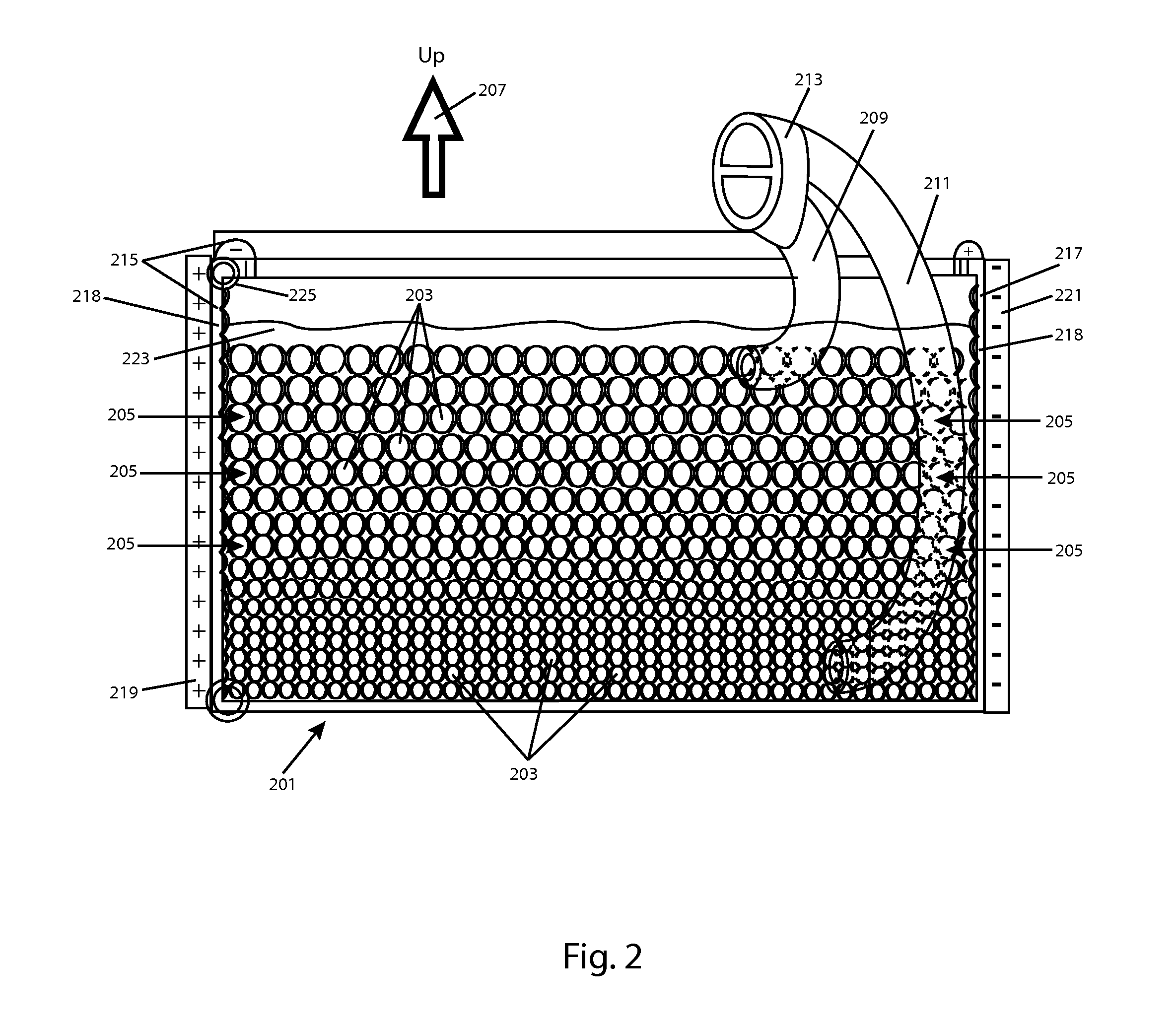
[0006]Density or other differentials between charged and discharged elements may aid in placing them in proper series (with similar charge states and capacities) and in separating them from one another for removal during replacement. For example, in some aspects, cells attain a final electrostatic charge differential that may drive compression of the cell, to increase its density upon discharge, or vice versa. In others, a discharged battery may attain an electrochemical state that leads it to bind with denser or lighter materials or materials that are more easily filtered or moved (carriers). Such carrier and filtration methods exploit an existing difference between charged and discharged cells, such as salt content in the electrolyte affecting its diamagnetism and motility in a variable magnetic field.
[0008]Aspects of the invention also provide for rapid exchange of larger, streamlined battery elements, without the use of an immersive fluid, and the systematic control of recharging balances accomplished by such exchanges.

Problems solved by technology

To this day, rechargeable batteries face difficult challenges and are thought by many to be a relatively impractical power source for high-power, high-capacity applications.
Among other challenges, each rechargeable battery has its own unique discharge and optimal recharging profile (“curve”), requiring specialized hardware to carefully control, and requiring significant time to accomplish.
If sub-optimal discharge takes place, a significant amount of power is lost in waste heat.
That waste heat, if mismanaged, can lead to catastrophic events, such as fires that destroy the appliance and injure users.
Incorrectly applied recharge currents, even in batteries designed to be recharged, may result in catastrophic events—such as explosion due to electrolysis releasing gas.
Charge management structures are generally too expensive to overcome the challenges in this regard.

Method used


Image

  • Rapid battery replacement and recharging techniques (CellGel)
  • Rapid battery replacement and recharging techniques (CellGel)
  • Rapid battery replacement and recharging techniques (CellGel)

Examples


Embodiment Construction

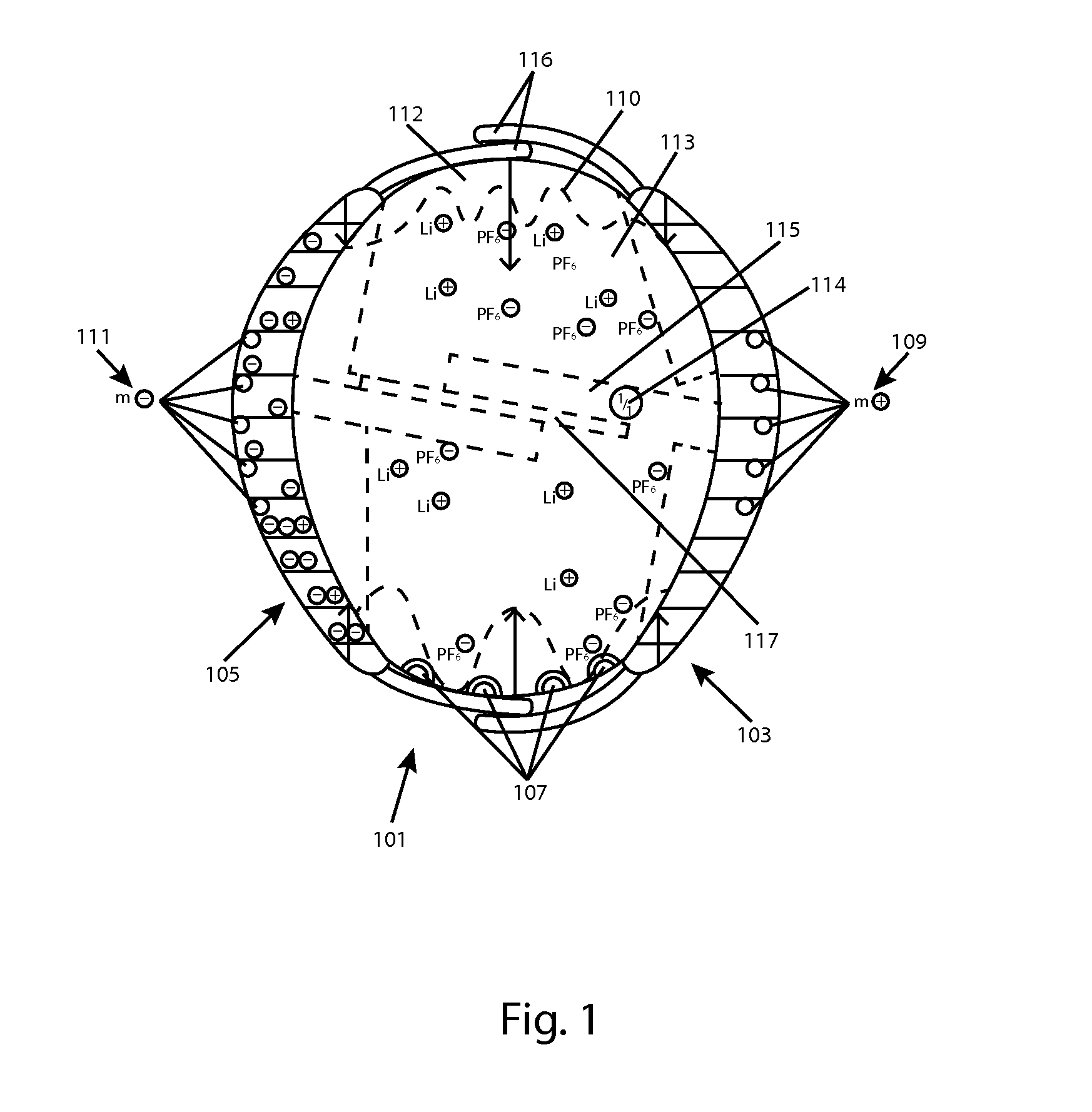
[0020]FIG. 1 is a side view of an exemplary battery cell 101 that may be used along with several other such cells, in a charging gel or fluid, in accordance with aspects of the invention. Cell 101 is a complete battery, capacitor or other device able to deliver a current for use in an appliance. The precise form of Cell 101 is illustrative only, and many other alternate forms may be used to carry out aspects of the invention.

[0021]Among its capabilities, cell 101 may deliver an electrical current from a cathode 103, and through a circuit, and receive current to an anode 105 (each an electrode). Electrodes 103 and 105 each have a multi-valent, curved outer contact area, which contribute to the overall curved and generally spherical or otherwise streamlined shape of cell 101. However, in some embodiments, cell 101 may alter its density, for example, by expanding and / or contracting depending upon its charge condition, as will be discussed in greater detail, below. Electrodes 103 and 10...


PUM

PropertyMeasurementUnit
widthaaaaaaaaaa
chargeaaaaaaaaaa
electrical poweraaaaaaaaaa

Abstract

New electrochemical battery recharging, refurbishment and replacement techniques are provided. In some aspects of the invention, small, fungible battery elements may be immersed in a fluid and delivered via a bifurcated pump interface that simultaneously unloads discharged cells and loads new, charged cells, to accomplish rapid cell replacement and recharging. The cells may be magnetically aligned to bring cathode and anode elements together, in series, and bridge contacts within a container (powering an appliance). Density differentials between charged and discharged elements may aid in placing them in series (with similar charge states and capacities) and in removing them during replacement.In other aspects, electrode elements may be rapidly flushed to accomplish rapid recharging, in a staged process. Aspects of the invention also provide for rapid exchange of larger, streamlined battery elements, without the use of an immersive fluid, and systematic control of recharging balances accomplished by such exchanges.

Description

FIELD OF THE INVENTION[0001]The present invention relates to the field of electrochemical batteries and, more specifically, rechargeable batteries.BACKGROUND[0002]Electrochemical batteries (“batteries”), which provide a stable, continuous electrical current to a circuit from a chemical energy source, have been in use at least since the early 1800s, when Allesandro Volta invented the voltaic pile. In a battery, internal chemical reactions (such as an oxidation / reduction reaction) drive electrons (and, therefore, a negative net charge) to an electrical contact called an anode, and a positive charge to another electrical contact called a cathode. By bridging the anode and cathode with an electrical conductor, a circuit is formed, which may include an appliance, and electrical current flows from cathode to the anode, powering such an appliance. As the battery discharges its current, the internal chemical reaction, and the battery itself, is eventually depleted and must be replaced or re...

Claims


Application Information

Patent Timeline
Patent Type & Authority Patents(United States)
IPC IPC(8): H01M10/42B60L11/18H01M10/058H01M2/02H01M10/04H01M10/38H01M2/20H01M4/02H01M10/052H01M2/38H01M50/107H01M50/51
CPCH01M10/049H01M10/058H01M10/4214H01M10/4242H01M10/4207B60L11/1822B60L11/1824B60L11/1827B60L11/1835H01M2/024H01M2/025B60L2240/622H01M2/208H01M2/38H01M10/052H01M10/38H01M2004/021H01M2004/025H01M2010/4271H01M2220/20Y02T10/7005Y02T10/7011Y02T10/7072Y02T10/7291Y02T90/121Y02T90/124Y02T90/125Y02T90/14Y02T90/16Y02T90/162Y10T29/53022Y10T29/53265B60L53/80B60L53/35B60L53/37B60L53/305B60L53/67B60L53/68Y02E60/10Y02T10/70Y02T10/72Y02T90/12Y04S30/12Y02T90/167H01M50/138H01M50/70Y02P70/50H01M50/51H01M50/107
Inventor BECKMAN, CHRISTOPHER V.
Owner BECKMAN CHRISTOPHER V
Features
  • R&D
  • Intellectual Property
  • Life Sciences
  • Materials
  • Tech Scout
  • Unparalleled Data Quality
  • Higher Quality Content
  • 60% Fewer Hallucinations
Learn More