Method and system for compensating for a time discrepancy

a time discrepancy and compensation method technology, applied in traffic control systems, multiplex communication, instruments, etc., can solve problems such as 3 m error, disadvantageous vehicle-to-x communication systems known from the prior art, and ready for large-scale production, so as to increase the reliability and precision of inventive compensation for time discrepancies. the effect of additional expenditure and simple determination

Active Publication Date: 2016-10-04
CONTINENTAL TEVES AG & CO OHG
View PDF9 Cites 1 Cited by
  • Summary
  • Abstract
  • Description
  • Claims
  • Application Information

AI Technical Summary

Benefits of technology

[0012]This results in the advantage that precise temporal classification of the received vehicle-to-X data and the events described by the vehicle-to-X data is made possible, since the method according to the invention compensates for the time discrepancy using the correction value. On the basis of this precise temporal classification, it is possible to improve the effectiveness and the efficiency of numerous driver assistance systems.
[0014]In addition, it is preferred that the first and second vehicle-to-X communication systems resort to a time base of a global navigation satellite system as external time base. Since a large number of new vehicles are already equipped with position finding apparatuses through a global navigation satellite system, such as GPS, as standard, these vehicles therefore have the opportunity to resort the time base of the GPS without additional expenditure. A further advantage can be seen in that the time base of a global navigation satellite system is comparatively precise.
[0016]Similarly, the first vehicle-to-X communication system sends the vehicle-to-X data usually only once per operating cycle. Since the operating cycles of the vehicle-to-X communication system and the ambient sensor system are in most cases different from one another, however, apparent continuity can nevertheless be produced by the interpolation or extrapolation of the ambient sensor data and the vehicle-to-X data. Looking for identical events that are described both in the ambient sensor data and in the received vehicle-to-X data and comparing the time stamps therefore allows the time discrepancy to be determined. By way of example, temporal interpolation takes place in the form that a straight line is drawn between two pieces of position information from a surrounding vehicle that are received by means of the vehicle-to-X communication system, the course of the straight line having a high probability of corresponding to the actual position of the surrounding vehicle during the time between the sending of the two pieces of position information. This results in the advantage that the time discrepancy or the correction value can be determined even in cases in which the ambient sensor data, owing to the clocked manner of operation of the ambient sensor system using the second time stamp, denote only discrete instants at which there are no received vehicle-to-X data available.
[0019]Expediently, the consistency checking involves the use of a piece of position information from captured distance data from a distance sensor and a piece of position information from received vehicle-to-X data. Since many vehicles already have distance sensors as standard, it is possible for the position information to be determined from captured distance data and checked for consistency with the position information from the received vehicle-to-X data without additional expenditure in terms of cost and manufacture. To this end, it is usually also necessary for the relative position information from the distance data from the distance sensor to be converted into an absolute position, as typically contained in the vehicle-to-X data, or vice versa. The pieces of position information are furthermore comparatively simple to determine.
[0020]Preferably, the consistency checking is based on a multiplicity of ambient sensor data records averaged using one or more statistical averaging methods. This increases the reliability and precision of the inventive compensation for the time discrepancy, since measurement errors and what are known as data outliers are neutralized on average.
[0041]The cited connection types afford different advantages, depending on type, wavelength and data protocol used. Thus, some of the cited connection types allow a comparatively high data transmission rate and comparatively fast connection setup, for example, whereas others are, to the greatest possible extent, well suited to data transmission around visual obstacles. The combination and simultaneous or parallel use of a plurality of these connection types result in further advantages, since in this way it is also possible to compensate for disadvantages of individual connection types.

Problems solved by technology

By contrast, what are not yet ready for large-scale production are what are known as vehicle-to-X communication systems, the extensive introduction of which, at least for new vehicles, has already been decided upon for the years to come, however, and which are currently still subject to standardization efforts.
However, even when the time base from a global satellite navigation system is used as a shared time base, the vehicle-to-X communication systems known from the prior art are disadvantageous insofar as the different satellite navigation reception modules have different processing periods and processing methods for the satellite signals received, depending on the manufacturer.
At a vehicle speed of approximately 100 km / h, a time discrepancy of 100 ms already results in a position error of 3 m, which is inadequate, particularly for safety-critical vehicle applications.

Method used


Image

  • Method and system for compensating for a time discrepancy
  • Method and system for compensating for a time discrepancy
  • Method and system for compensating for a time discrepancy

Examples


Embodiment Construction

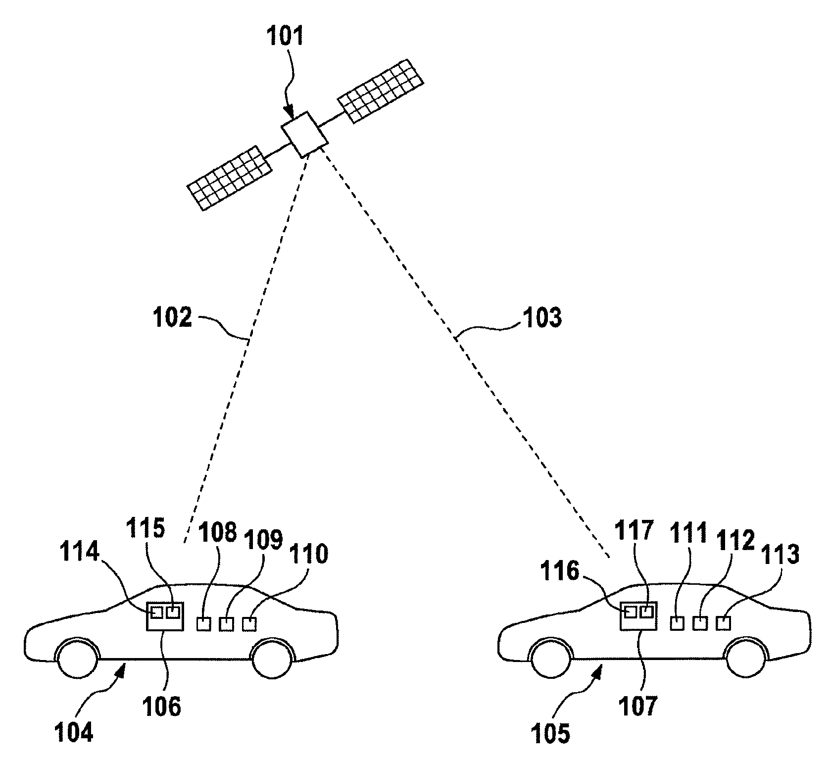
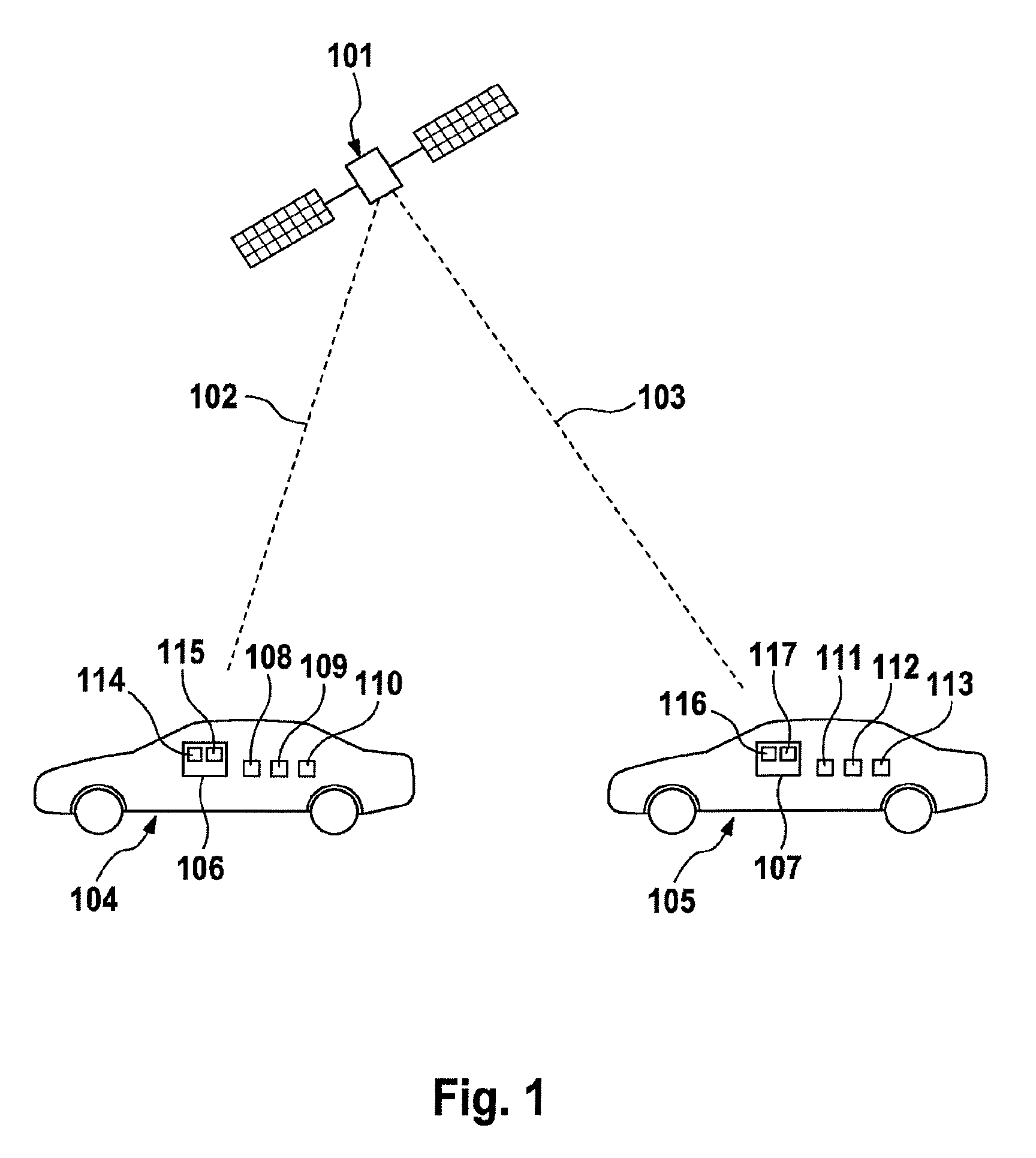
[0048]FIG. 1 shows GPS satellite 101, which is used, according to the example, as an external timer and sends identical GPS signals 102 and 103 to communication subscribers 104 and 105. According to the example, communication subscribers 104 and 105 are motor vehicles, wherein communication subscriber 104 comprises first vehicle-to-X communication system 106 and communication subscriber 105 comprises second vehicle-to-X communication system 107. Communication subscriber 104 additionally comprises ambient sensors 108, 109 and 110 in the form of mono camera sensor 108, ultrasonic sensor 109 and radar sensor 110 and communication subscriber 105 comprises ambient sensors 111, 112 and 113 in the form of radar sensor 111, lidar sensor 112 and stereo camera sensor 113. First vehicle-to-X communication system 106 for its part comprises first internal timer 114 and electronic consistency checking means 115, while second vehicle-to-X communication system 107 for its part comprises second inte...


PUM


Abstract

A method and system for compensating for a time discrepancy. A first and a second vehicle-to-X communication system resort to an external time base. The first vehicle-to-X communication system determines a first internal time base from the external time base and the second vehicle-to-X communication system determines a second internal time base from the external time base. The first vehicle-to-X communication system sends vehicle-to-X data and the second vehicle-to-X communication system receives vehicle-to-X data. The vehicle-to-X data to be sent include a time stamp generated from the first internal time base and captured ambient sensor data include a first time stamp generated from the second internal time base. Alignment of the captured ambient sensor data with the received vehicle-to-X data is used to determine the time discrepancy between the first internal time base and the second internal time base and to compensate for it using a correction value.

Description

CROSS REFERENCE TO RELATED APPLICATIONS[0001]This application is the U.S. National Phase Application of PCT International Application No. PCT / EP2013 / 067096, filed Aug. 15, 2013, which claims priority to German Patent Application No. 10 2012 214 555.9, filed Aug. 16, 2012, the contents of such applications being incorporated by reference herein.FIELD OF THE INVENTION[0002]The invention relates to a method for compensating for a time discrepancy and to a system for compensating for a time discrepancy.BACKGROUND OF THE INVENTION[0003]A large number of different ambient sensors in motor vehicle applications are known from the prior art. These are seeing increasingly widespread use on account of the many and diverse new opportunities that such sensor systems provide in connection with driver assistance systems. The ambient sensors used in this case are radar sensors, camera sensors and lidar sensors, for example. Similarly, navigation systems, which are usually of GPS-based design, are a...

Claims


Application Information

Patent Timeline
Patent Type & Authority Patents(United States)
IPC IPC(8): H04B7/212H04J3/06G08G1/01H04B7/185
CPCH04J3/0644G08G1/0112H04B7/18513H04J3/0667H04J3/0682
Inventor STAHLIN, ULRICH
Owner CONTINENTAL TEVES AG & CO OHG
Why Eureka
Try Eureka