Objective phoropter system

a phoropter and objective technology, applied in the field of ophthalmic measurement apparatus, can solve the problems of difficult to accurately perform subjective phoropter measurement alone, difficult to measure retinal reflection, and great difficulty in optimizing a function (the subject's vision), so as to reduce the effect of reflection, accurate measurement, and better correction

Active Publication Date: 2016-10-11
VISIONIX
View PDF12 Cites 11 Cited by
  • Summary
  • Abstract
  • Description
  • Claims
  • Application Information

AI Technical Summary

Benefits of technology

[0010]Secondly, after passage through the phoropter, the corrected wavefront is closer to being a planar wavefront, and the residual aberration left for measurement by the wavefront analyzer is small and therefore accurately measurable. Although most wavefront measurement systems incorporate a lens for correction of power of the eye, such that the measurement is generally made on a reasonably corrected eye, the currently proposed combination system has the advantage of additionally providing cylinder correction, providing a much better corrected eye on which the wavefront analysis is performed.
[0031]Alternatively, the axial position of the focusing system may be adjusted such that the beam of corneal reflected light is focused onto the wavefront analyzer in the central region of the wavefront analyzer. In such a situation, when the axial position of the focusing system is adjusted such that the beam of corneal reflected light is focused onto the wavefront analyzer in the central region of the wavefront analyzer, light reflected from the retinal surface of the eye is arranged to form an essentially collimated beam at the wavefront analyzer, such that the aberrations of the eye can be measured from the deviations of the wavefront. This essentially collimated beam may enter the wavefront analyzer over a substantially larger area of the wavefront analyzer than the central region of the wavefront analyzer, such that the corneal reflected light does not flood out the retinally reflected light entering the wavefront analyzer over the substantially larger area.

Problems solved by technology

In its path through the phoropter elements, part of the incident laser light may be reflected back towards the Shack-Hartmann detection array, and the intensity of this reflected light may be substantially larger than that of the weak reflection from the retina, making measurement of the retinal reflection difficult.
Firstly, a subjective phoropter measurement alone can be difficult to perform accurately, especially for vision defects with significant higher order aberration content, because of the dependence of the measurement on the subject's subjective response.
Furthermore, even if the subjective response were accurate, there is great difficulty in optimizing a function (the subject's vision) when three or more variables (the lenses or prisms of the three or more phoropter wheels) need to be changed alternately and iteratively to reach the situation of minimal aberrations, especially in the presence of significant higher order aberrations.

Method used


Image

  • Objective phoropter system
  • Objective phoropter system
  • Objective phoropter system

Examples


Embodiment Construction

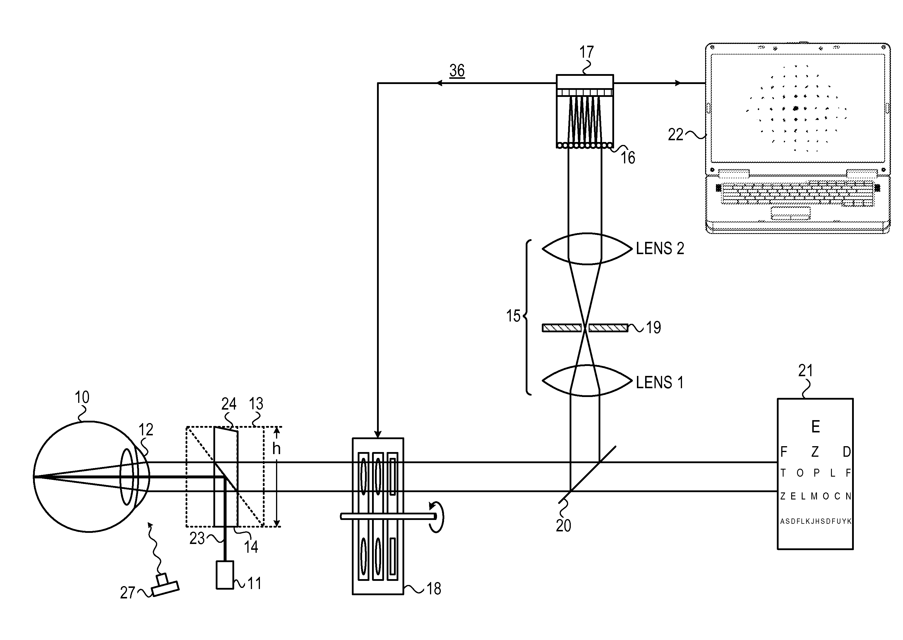
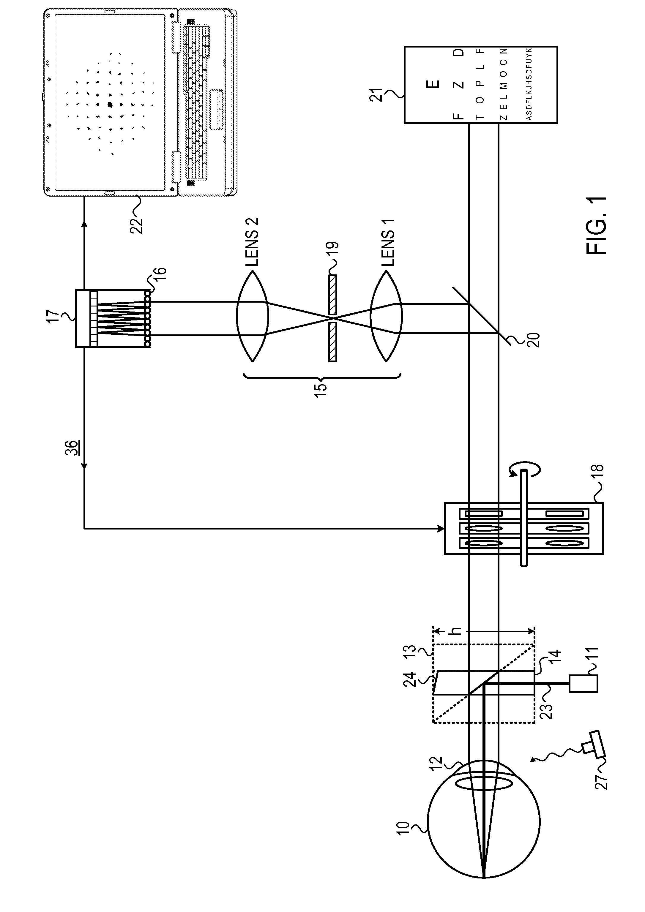
[0048]Reference is now made to FIG. 1, which illustrates schematically an example of a combined phoropter / wavefront analysis system of the type disclosed in this application. The subject's eye 10 is illuminated by means of a laser 11, though any other suitable collimated light source could be used, whose beam is directed into the eye by means of a beam splitter 14 located immediately in front of the subject's eye. The illumination is focused by the eye's optics towards the subject's retina, and the light reflected from the retina passes back through the optics of the eye, back through the input illumination beam splitter 14, and through the lens wheels of a phoropter 18. It may then be directed by a second beam splitter 20, away from the direct line of sight of the subject, and is optically focused through a pinhole beam aperture 19 disposed between a pair 15 of focusing lenses LENS1 and LENS2, and is directed into a Shack-Hartmann (SH) detector array. This most conveniently incorpo...


PUM


Abstract

Systems for performing combined phoropter and refractive measurements to ascertain the aberrations present in the eye of a subject. The systems use a pair of phoropter wheel assemblies, one for each eye, each assembly comprising a number of lens wheels incorporating the series of lenses and wedges required to compensate for a range of refractive vision aberrations. The vision of each eye is corrected by a combination of a subjective phoropter measurement, iteratively performed with an objective wavefront analysis measurement to determine the residual aberrations existing after the initial phoropter correction. The system is able to automatically align the axes of each wavefront analyzer with is corresponding eye, by means of centering the pupil image in the wavefront analyzer camera, and to determine the pupil distance. By changing the focusing point on the wavefront analyzer of the light reflected from the eye, the corneal profile can be measured.

Description

CROSS-REFERENCE TO RELATED APPLICATIONS[0001]This application is a U.S. National Phase Application under 35 U.S.C. 371 of International Application No. PCT / IL2013 / 000037, which has an international filing date of Apr. 4, 2013, and which claims priority from U.S. Provisional Patent Application No. 61 / 686,426, filed Apr. 5, 2012, the contents of which are incorporated herein by reference in their entirety.FIELD OF THE INVENTION[0002]The present invention relates to the field of ophthalmic measurement apparatus, especially that combining phoropter measurements and wavefront analysis, such that a phoropter measurement can be performed more objectively.BACKGROUND OF THE INVENTION[0003]There are two main methods of determining the refractive properties of an eye for the purpose of providing correction lenses. One of those methods is subjective and the other objective. The subjective method is that of the familiar phoropter, in which the subject is asked to view a test plate, while optical...

Claims


Application Information

Patent Timeline
Patent Type & Authority Patents(United States)
IPC IPC(8): A61B3/10A61B3/02A61B3/028
CPCA61B3/0285A61B3/1015F04C2270/041
Inventor ABITBOL, MARCYAM, RANHERMAN, HAGGAIMELNICK, IAN
Owner VISIONIX
Why Eureka
Try Eureka