Adjustable continuous filament structure and method of manufacture and use

a technology of continuous filament and adjustable structure, which is applied in the direction of yarn, textiles and papermaking, thin material processing, etc., can solve the problems of compromising repair, increasing the incidence of suture breakage, and increasing the number of knots needed

Active Publication Date: 2016-10-11
STRYKER CORP +1
View PDF594 Cites 12 Cited by
  • Summary
  • Abstract
  • Description
  • Claims
  • Application Information

AI Technical Summary

Benefits of technology

[0005]Generally, the present invention includes devices, assemblies, systems, kits and methods of manufacture, assembly and use for the repair of soft tissue. Specifically, in one embodiment, the present invention includes a suture device constructed of a continuous filament having a continuous, adjustable loop configuration. Further, the adjustable loop configuration can be adjusted using a single free strand which may provide for simplified, reliable use in the repair of soft tissue, such as, in one embodiment, securing an ACL graft within a bone tunnel.
[0015]Additionally, the method may include the step of passing the second filament, second anchor and graft into tibial tunnel such that the second anchor engages a lateral cortex of the tibia. Also, the method may include the step of tensioning the single free segment of the second filament to shrink the adjustable portion of the second filament and further tension the graft between the anchor and second anchor.
[0016]Continuing with this embodiment, the single line of filament may include a one-way feature such that the single free segment can be tensioned to shrink the adjustable portion, but the one-way feature may prevent the adjustable portion from expanding due to tension applied to the adjustable portion.
[0018]Further, the single line of filament may include a one-way feature such that the single free segment can be tensioned to shrink the adjustable portion, but the one-way feature may prevent the adjustable portion from expanding due to tension applied to the adjustable portion.

Problems solved by technology

The decrease in the number of knots needed in a surgery is important as there is always a chance a knot may loosen or come undone, thereby compromising the repair.
Additionally, the knot itself can create a weakened area which may result in a higher incidence of suture breakage.
Currently, a challenge in the suture art is developing a continuous suture loop that can be affixed to a suture anchor, tissue, or the like in an efficient manner.
For example, issues tend to arise when using continuous suture loops when an operator (e.g., a surgeon or the like) attempts to obtain a desired tension on the soft tissue.
This is particularly difficult in a repair of a torn anterior cruciate ligament (ACL) in a knee of a patient.
This is often times difficult to achieve and thus, has a tendency to reduce the effectiveness of such repairs.
Additionally, when a standard continuous suture loop is utilized, the operator must carefully select the appropriate loop length and tunnel depth based on the size of the graft and the patient's anatomy, which may increase the risk of error or increase procedure length.
Furthermore, current continuous suture loops can be difficult to secure to a suture anchor, suture button, or the like.
The cacophony of filament produced by these devices in conjunction with external structures may increase the likelihood of snagging and increase the number of components, thereby increasing the probability of failure of one of these components.
Further, the surgeon must divert his or her focus in order to ensure the adjustable suture loop does not become entangled with itself or other structures, oftentimes with limited success.

Method used


Image

  • Adjustable continuous filament structure and method of manufacture and use
  • Adjustable continuous filament structure and method of manufacture and use
  • Adjustable continuous filament structure and method of manufacture and use

Examples


Embodiment Construction

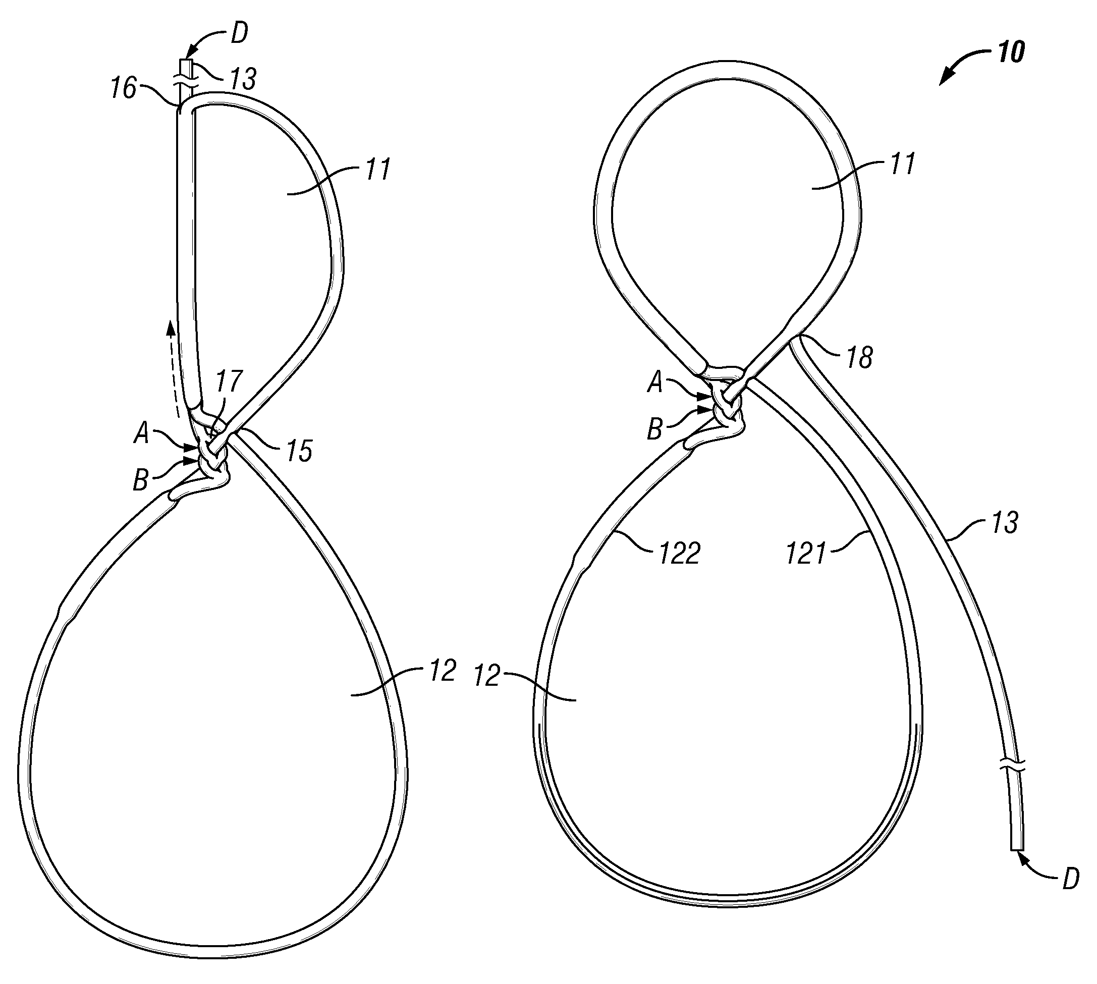
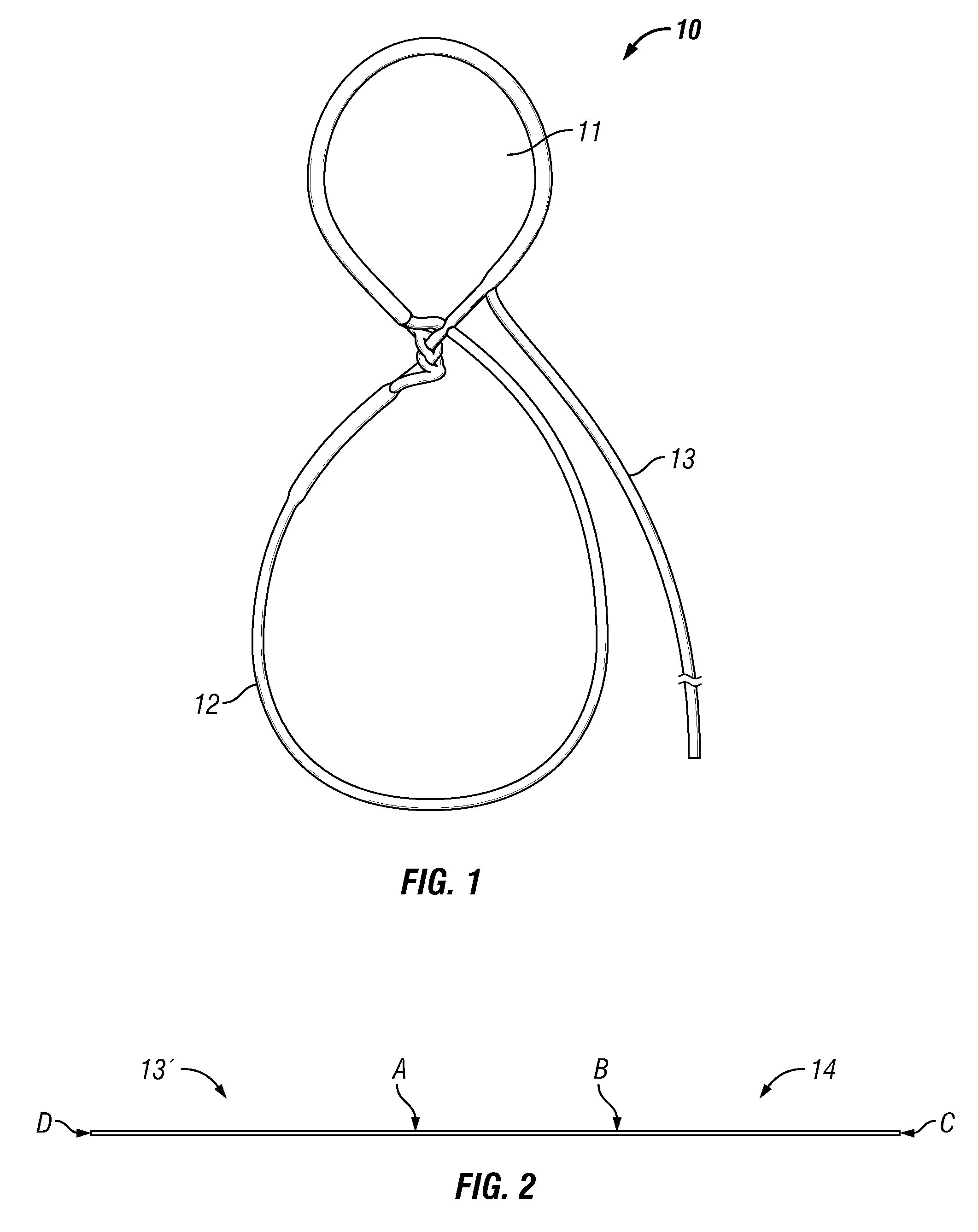
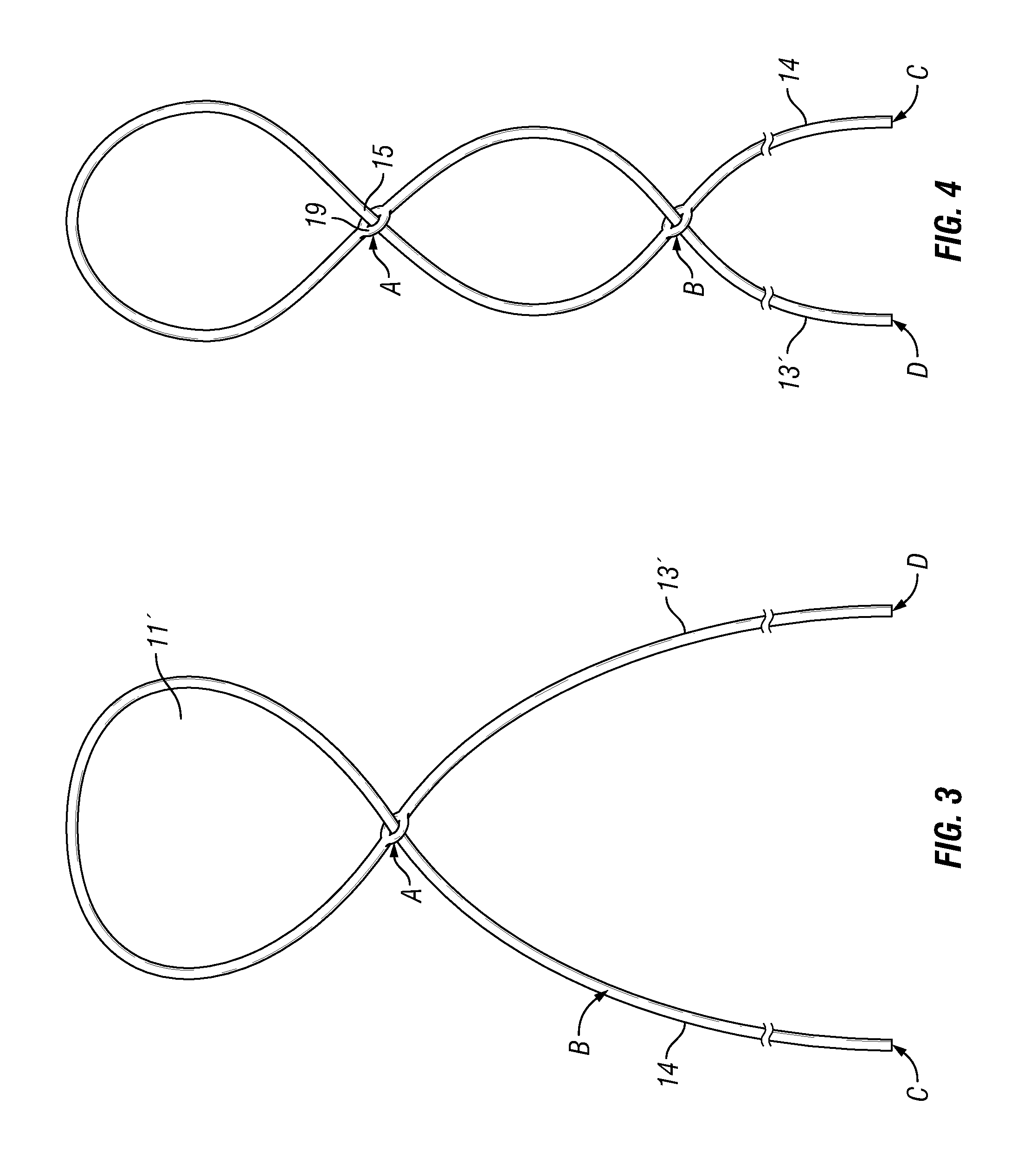
[0026]FIG. 1 depicts one embodiment of a suture device or assembly 10. As shown, suture device 10 includes a nonadjustable portion 11, an adjustable portion 12, and a single free strand 13. The suture device 10 may be constructed from a single, continuous, line of filament, preferably with a hollow core along at least a portion of its length. As used herein, “filament” or “filamentary” is defined as a suture or other thread-like material having a hollow core along at least a portion of its length. Preferably, the “filament” is a braided suture having a hollow core along its length. As used herein, “continuous” is defined as a single length of material, or preferably, s single length of braided, hollow suture. The single line of filament may be constructed from homogenous or heterogeneous materials such as, but not limited to, polyester, polyethylene (including ultra-high molecular weight polyethylene (UHMWPE)), polytetrafluorethylene (including expanded polytetrafluorethylene), nylo...


PUM

PropertyMeasurementUnit
tensionaaaaaaaaaa
lengthaaaaaaaaaa
sizeaaaaaaaaaa

Abstract

A method of assembling an adjustable continuous filament assembly whereby a single length of filament is spliced to form a nonadjustable portion and a single free segment. The single free segment is introduced into the inner core of the nonadjustable portion at a first position. The single free segment is passed through at least a portion of the inner core of the nonadjustable portion. The single free segment is withdrawn from the nonadjustable portion at a second position, thereby forming an adjustable portion secured to the nonadjustable portion and adjustable by the single free segment.

Description

BACKGROUND OF THE INVENTION[0001]The use of continuous, closed suture loops has been incorporated in soft tissue surgeries in recent years, particularly since the proliferation of the use of knotless anchors. The decrease in the number of knots needed in a surgery is important as there is always a chance a knot may loosen or come undone, thereby compromising the repair. Additionally, the knot itself can create a weakened area which may result in a higher incidence of suture breakage.[0002]Currently, a challenge in the suture art is developing a continuous suture loop that can be affixed to a suture anchor, tissue, or the like in an efficient manner. For example, issues tend to arise when using continuous suture loops when an operator (e.g., a surgeon or the like) attempts to obtain a desired tension on the soft tissue. This is particularly difficult in a repair of a torn anterior cruciate ligament (ACL) in a knee of a patient. In such a repair, the operator must properly tension the...

Claims


Application Information

Patent Timeline
Patent Type & Authority Patents(United States)
IPC IPC(8): A61B17/06D02G3/44B65H69/06A61B17/04
CPCA61B17/06166A61B17/0401A61B17/0469A61B17/0485B65H69/06D02G3/448A61B2017/0404A61B2017/0462A61B2017/0496
Inventor PILGERAM, KYLE CRAIGPADILLA, LUISVODNICK, AARONLONGERICH, RANDY
Owner STRYKER CORP
Why Eureka
Try Eureka