Carbon dioxide chemical absorption system installed with vapor recompression equipment

a chemical absorption system and carbon dioxide technology, applied in chemical apparatus and processes, separation processes, dispersed particle separation, etc., can solve the problems of deterioration or loss of absorbing solution, difficult to employ the method as an efficient method of heat source use, etc., to suppress the deterioration of absorbing solution, reduce the amount of water vapor, and improve the effect of plant thermal efficiency

Active Publication Date: 2016-10-11
MITSUBISHI HITACHIPOWER SYST LTD
View PDF7 Cites 0 Cited by
  • Summary
  • Abstract
  • Description
  • Claims
  • Application Information

AI Technical Summary

Benefits of technology

[0029]Since each of a carbon dioxide (CO2) chemical absorption system installed with a vapor recompression equipment and an exhaust gas treatment system comprising the carbon dioxide chemical absorption system in the present invention is capable of using a vapor obtained by flash-evaporating a part of an absorbing solution withdrawn from a regeneration column as a heat source of the regeneration column by recompressing the vapor, each of the systems is capable of improving plant thermal efficiency by reducing an amount of water vapor to be fed to a reboiler 60. Further, each of the carbon dioxide chemical absorption system and the exhaust gas treatment system in the present invention is capable of suppressing deterioration of the absorbing solution otherwise caused by excessive heating without breaking a material balance inside a flash tank since a temperature control device adjusts a temperature of the recompressed vapor to be within a predetermined range (for example, 110° C. to 120° C.).

Problems solved by technology

Though the above-described conventional technology has the advantage of reusing the vapor recompressed by the recompressor 92 as the heat source by feeding the recompressed vapor to the regeneration column 40, the technology has the disadvantage of deterioration or loss of the absorbing solution since the absorbing solution is excessively heated due to the temperature increase in the regeneration column by the vapor fed to the regeneration column.
If the gas phase / liquid phase ratio was changed in order to change the vapor generation amount, a material balance in the flash tank 91 is lost to entail unstable feeding of the absorbing solution (liquid phase) to the CO2 absorption column 20 or generation of surplus vapor, thereby making it difficult to employ the method as an efficient method of using the heat source.

Method used


Image

  • Carbon dioxide chemical absorption system installed with vapor recompression equipment
  • Carbon dioxide chemical absorption system installed with vapor recompression equipment
  • Carbon dioxide chemical absorption system installed with vapor recompression equipment

Examples


examples

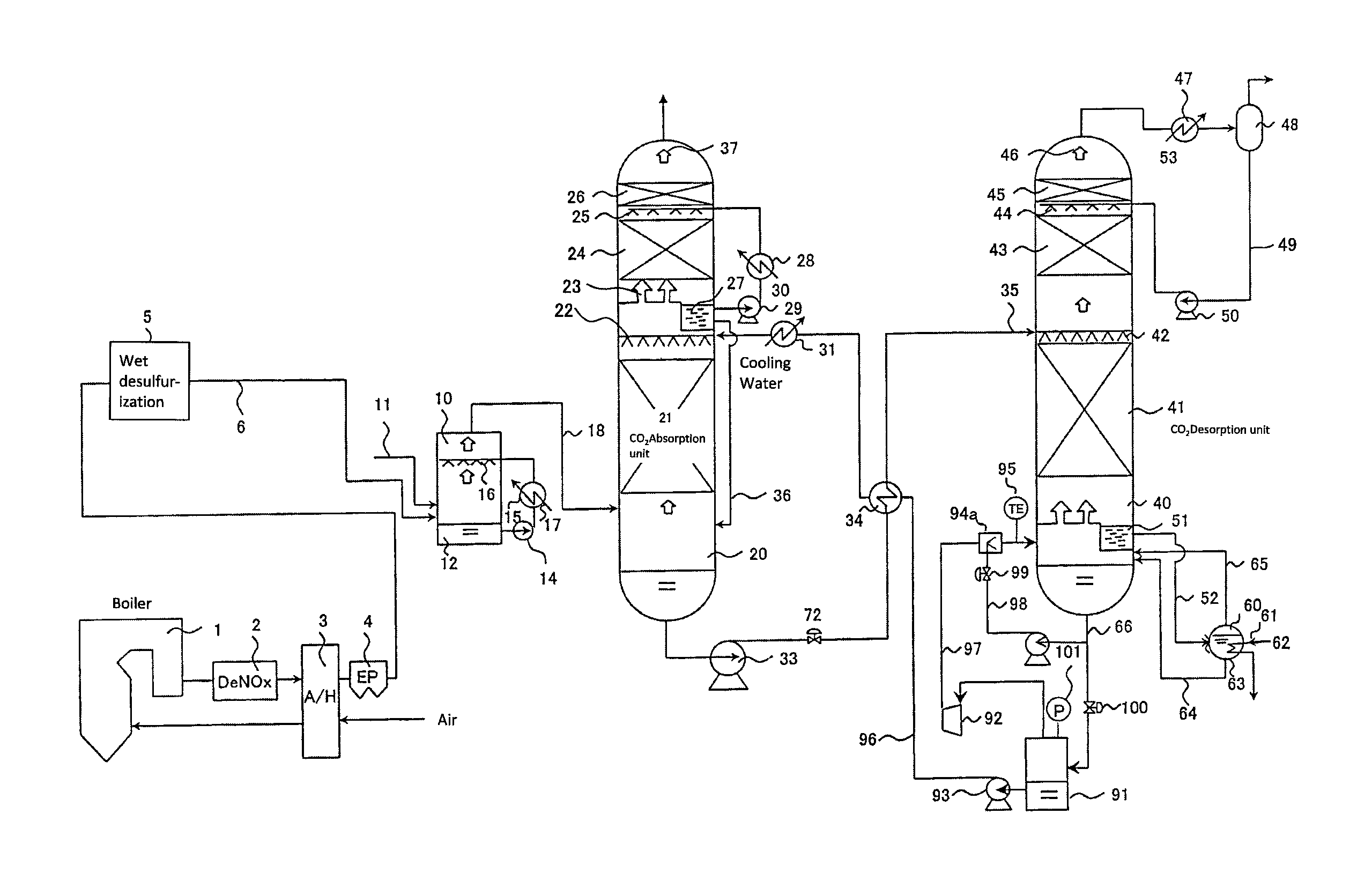
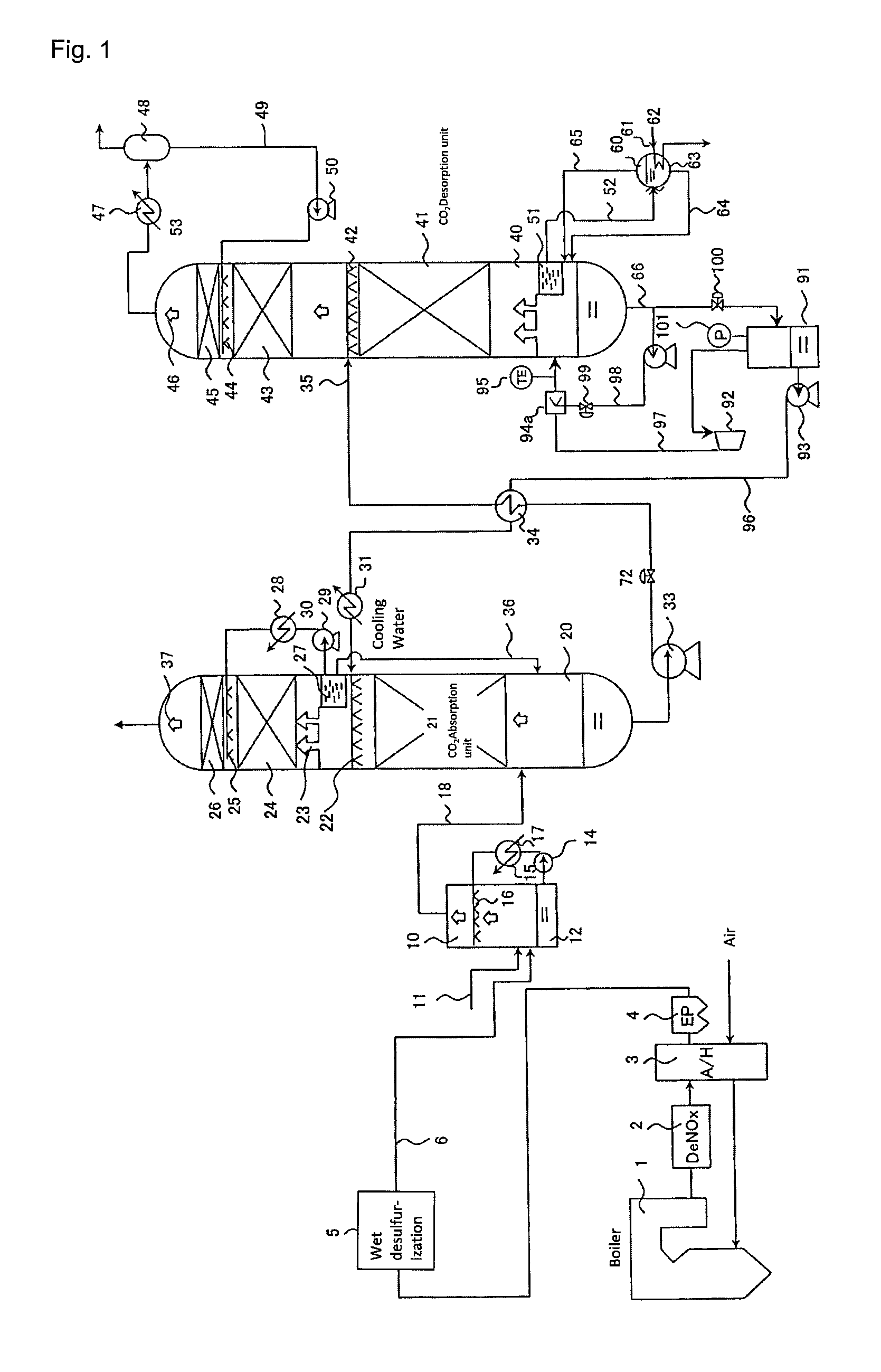
[0041]The present invention will be described in more details in conjunction with Embodiment 1 shown in FIG. 1.

[0042]Embodiment 1 according to the present invention is different from the embodiment according to the conventional technology shown in FIG. 8 in the feature that a part of an absorbing solution withdrawn from a regeneration column 40 is used as a coolant for cooling a vapor generated by a flash tank 91 and recompressed by a recompressor 92 and the like in order to control the vapor to be fed to the regeneration column 40 to an optimum temperature (for example, 110° C. to 120° C.). More specifically, as shown in FIG. 1, a branch piping 98 for partially withdrawing the absorbing solution from an absorbing solution withdrawal piping 66 extending from the regeneration column 40 to the flash tank 91 is installed. A cooler 94a is installed in a compressed vapor piping 97. The absorbing solution is sprayed by using a spray nozzle 98 and the like in the cooler 94a to bring the ab...


PUM

PropertyMeasurementUnit
temperatureaaaaaaaaaa
chemical absorptionaaaaaaaaaa

Abstract

An exhaust gas treatment system comprising: a CO2 chemical absorption equipment comprising an absorption column which absorbs carbon dioxide (CO2) in a combustion exhaust gas discharged from a combustion device with the use of an absorbing solution comprising an amine compound as a main component and a regeneration column which regenerates the absorbing solution by desorbing CO2 from the absorbing solution which absorbed CO2; a flash tank which depressurizes the absorbing solution withdrawn from a lower part of the regeneration column to flash-evaporate the absorbing solution; a vapor recompression equipment which compresses the vapor generated by the flash tank; a temperature control device which adjusts the vapor compressed by the vapor recompression equipment to be within a predetermined temperature; and a piping for feeding the vapor adjusted to the predetermined temperature by the temperature control device to the regeneration column.

Description

TECHNICAL FIELD[0001]The present invention relates to a carbon dioxide (CO2) chemical absorption system installed with a vapor recompression equipment. More specifically, the present invention relates to a carbon dioxide (CO2) chemical absorption system installed with a vapor recompression equipment and an exhaust gas treatment system comprising the carbon dioxide chemical absorption system, each of which is capable of utilizing a vapor obtained by flash-evaporating a part of an absorbing solution withdrawn from a regeneration column as a heat source of the regeneration column by recompressing the vapor and of suppressing deterioration of the absorbing solution otherwise caused by excessive heating by adjusting a temperature of the vapor to be within a predetermined range (for example, 110° C. to 120° C.).BACKGROUND ART[0002]A large amount of carbon dioxide is generated from a thermal power generation equipment or a boiler equipment due to combustion of a fuel such as coal and heavy...

Claims


Application Information

Patent Timeline
Patent Type & Authority Patents(United States)
IPC IPC(8): B01D53/14C01B32/50
CPCB01D53/1425B01D53/1475B01D53/1493B01D2252/204B01D2252/20478B01D2257/504B01D2258/0283Y02C10/04Y02C10/06Y02C20/40
Inventor TANIGUCHI, NORIAKISHIMAMURA, JUNKATSUBE, TOSHIOHIGASHI, HIDEAKI
Owner MITSUBISHI HITACHIPOWER SYST LTD
Why Eureka
Try Eureka