
Protective headgear

a headgear and protective technology, applied in the field of protective headgear, can solve the problems of prone to bottoming out of cells, ranging from mild concussion or mild traumatic brain injury (mtbi) to severe brain damage, and achieve the effect of facilitating the reduction of energy

Inactive Publication Date: 2016-10-18
FRASER JANICE GERALDINE +1
View PDF32 Cites 14 Cited by
  • Summary
  • Abstract
  • Description
  • Claims
  • Application Information

AI Technical Summary

Benefits of technology

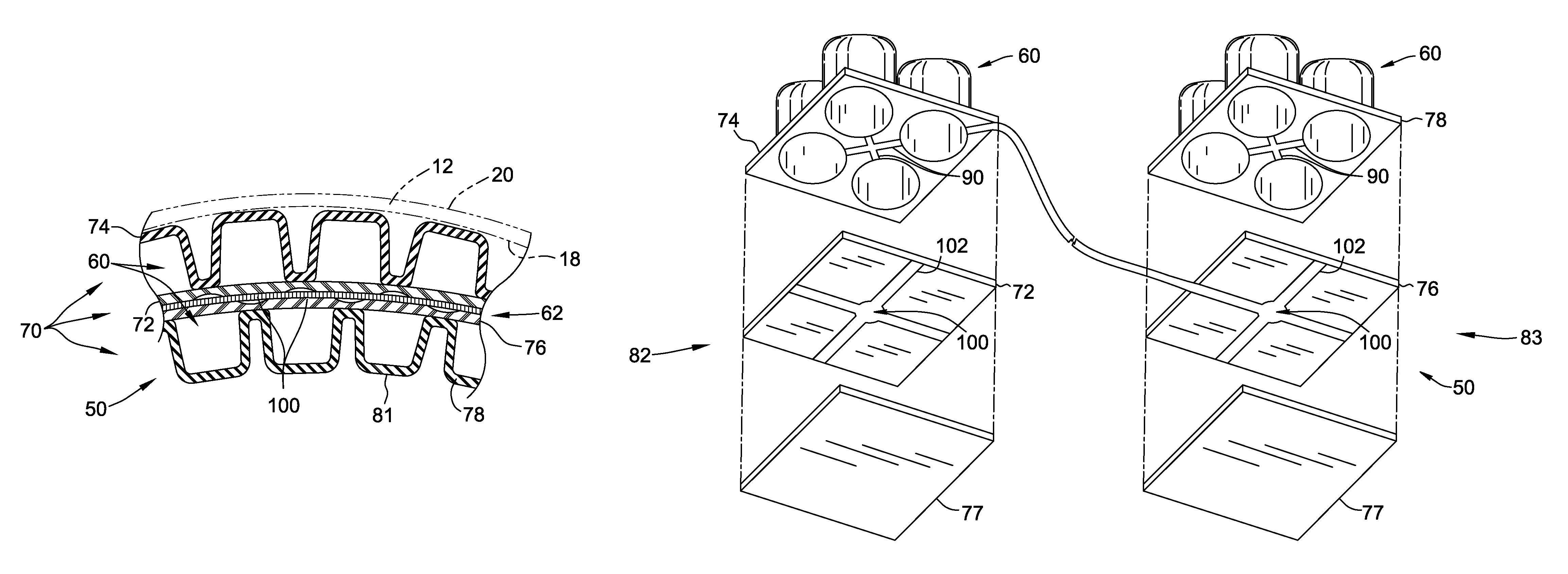
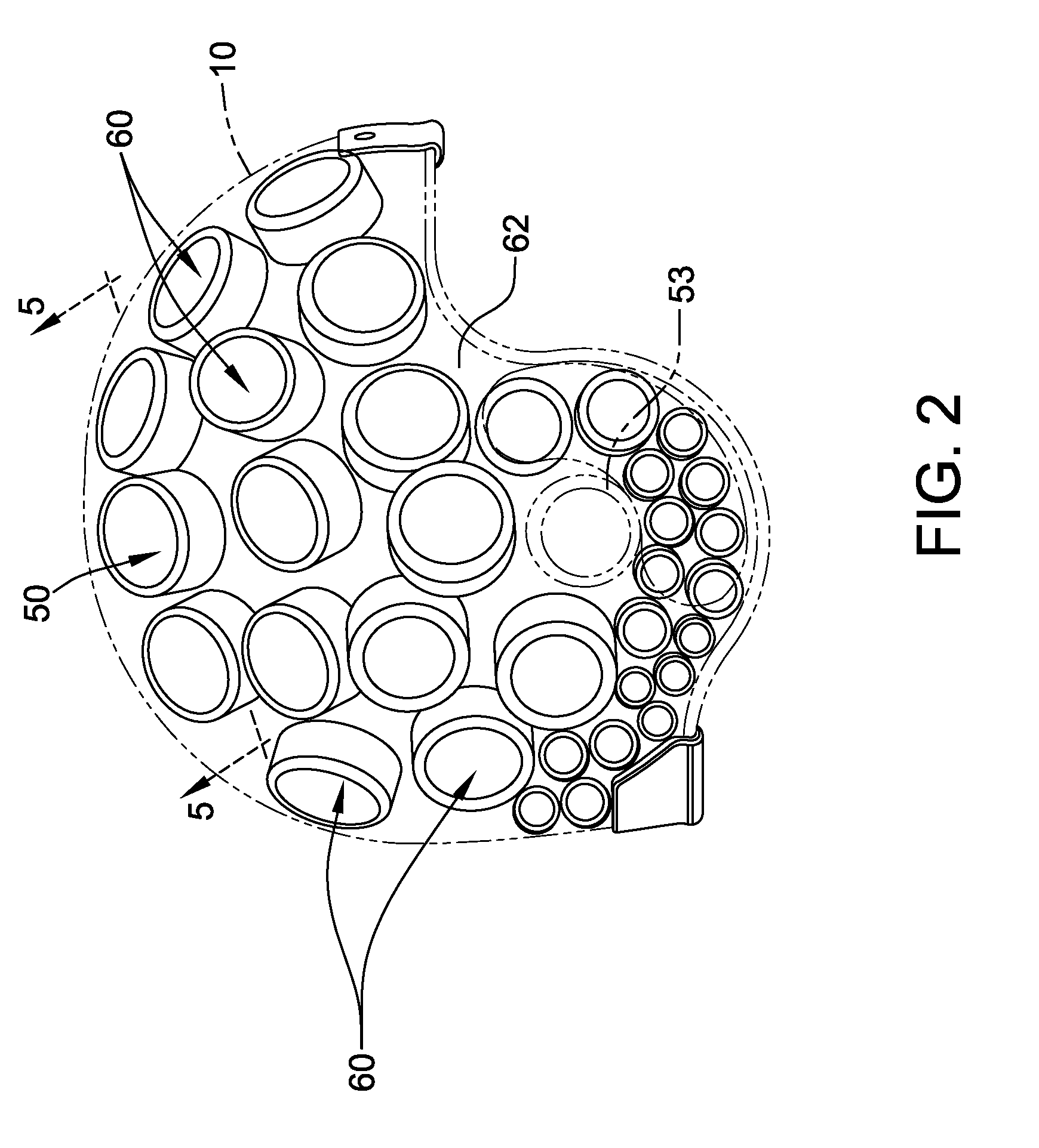
The patent describes a helmet with a flexible support system that conforms to the shape of the helmet shell. The support system has multiple hollow cells that are connected in flow communication with each other. This allows fluid to be transferred between the cells to reduce energy levels in the helmet wearer in case of an impact.

Problems solved by technology

Moreover, because brain damage is cumulative and is permanent, no corrective measure can undo damage resulting from a brain injury and as such, the focus of preventing such injuries from occurring has been elevated.
Such an impact may result in a skull fracture and / or mild traumatic brain injury (MTBI).
When an external impact shakes the brain inside the skull, the shaking may result in temporarily disrupting the brain from working normally by disturbing or damaging electrical, chemical, and / or anatomical function connections within the brain, which may result in MTBI.
Any impact energy not absorbed by the helmet is transferred to the skull of the wearer, which may result in injuries ranging from mild concussions or mild traumatic brain injury (MTBI) to severe brain damage.
However, depending on the size and density of the resilient material, such cells may be prone to bottoming out when compressed between the helmet and the wearer's head.
Once bottomed out, the energy absorption ability of such cells is limited at best.
Simply increasing the density of the compressible material and / or increasing the thickness of the cells may provide only limited benefits and may require significant increases in the overall size of the helmet.
As such, the energy-absorption capabilities and benefits of known helmets including such compression cells may be limited.

Method used


Image

  • Protective headgear
  • Protective headgear
  • Protective headgear

Examples


Embodiment Construction

[0016]Embodiments of the present disclosure relate to energy-absorption / dissipation systems implemented within various devices, components, systems, and processes to facilitate energy dissipation. In some embodiments, an energy-absorption system is implemented within support structures such as, but not limited to protective headgear, helmets, shoes, or other protective wear / clothing including baseball chest protectors, shin guards, and / or shoulder pads. In other implementations, the energy-absorption system is implemented in structures designed to absorb an impact, such as, but not limited to, crash barriers. As used herein, the term energy absorption system refers to systems that distribute energy from an impact over a larger area to facilitate dissipating the energy and to facilitate reducing impact loading induced to the wearer is substantially reduced. The embodiments described herein are exemplary and are not limited to the descriptions provided.

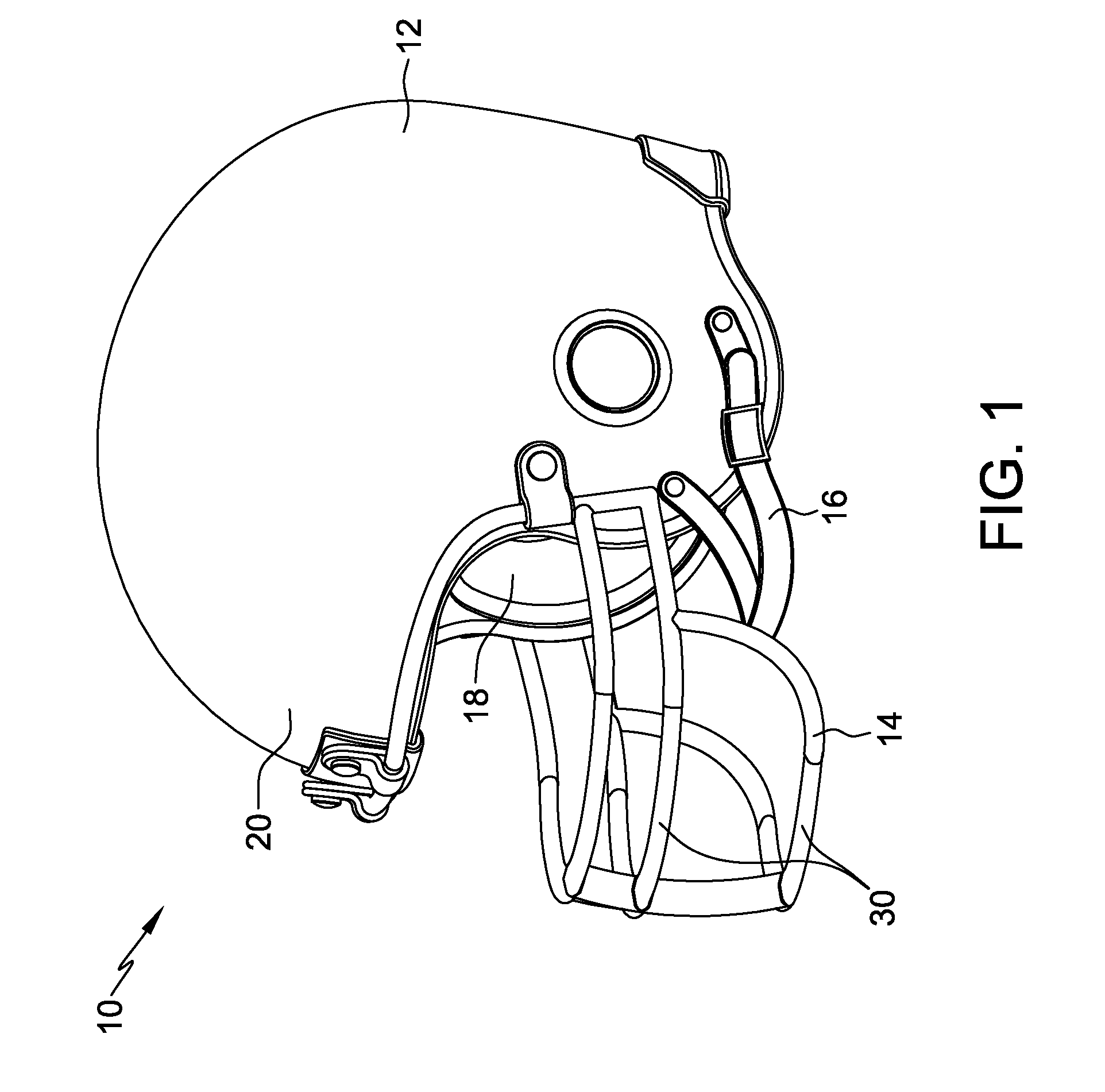
[0017]FIG. 1 is a perspective vi...


PUM

PropertyMeasurementUnit
flexibleaaaaaaaaaa
compressaaaaaaaaaa
dissipating energyaaaaaaaaaa

Abstract

A helmet including a shell and a support system is provided. The shell includes an outer surface and an inner surface. The support system includes a base and a plurality of hollow cells extending outward from the base. The support system substantially conforms to the shell inner surface. The cells are segmented into a plurality of regions wherein the cells within each of the regions are coupled together in flow communication via a plurality of channels extending therebetween. At least one cell within a first region is coupled in flow communication to at least one cell within a second region to enable fluid to be selectively transferred from at least some of the cells in the first region to at least some of the cells in the second region to facilitate reducing an amount of energy induced to a wearer of the helmet following an impact to the shell.

Description

BACKGROUND[0001]This invention relates generally to protective headgear, and more particularly, to headgear designed to facilitate reducing skull and brain injuries.[0002]Modern headgear, including helmets, is often worn by individuals during physical activities, including sporting events and exercise, to help protect the wearer from head injuries. At least some known head protective devices are manufactured to satisfy safety and / or legal regulations set by various federal and state agencies, and / or organizations governing specific activities. For example, military helmets may be manufactured to withstand different requirements than those required by professional sports organizations, such as Major League Baseball (MLB) or the National Football League (NFL). Generally, the efficacy of all protective headgear is constantly examined to facilitate enhanced head protection for the wearer. Moreover, because brain damage is cumulative and is permanent, no corrective measure can undo damag...

Claims


Application Information

Patent Timeline
Patent Type & Authority Patents(United States)
IPC IPC(8): A42B3/12B29C69/00
CPCA42B3/121B29C69/00
Inventor FRASER, JANICE GERALDINEREESER, III, ROBERT B.
Owner FRASER JANICE GERALDINE
Learn More