Motion limiting device and motion limiting method

a technology of motion limitation and limiting device, which is applied in the direction of computer control, program control, instruments, etc., can solve the problems of robots being in contact with obstacles, difficult for robots to avoid unobservable areas, and robots being in unexpected contact with obstacles, so as to reduce the distance between robots and obstacles

Active Publication Date: 2016-10-18
TOYOTA JIDOSHA KK
View PDF59 Cites 13 Cited by
  • Summary
  • Abstract
  • Description
  • Claims
  • Application Information

AI Technical Summary

Benefits of technology

[0007]The present invention has been made in order to solve these problems and aims to provide a motion limiting device and a motion limiting method capable of mitigating, even when the robot comes in contact with an obstacle in the unobservable area, an impact caused by the contact.
[0012]In this aspect, upon determining that the robot is within a predetermined distance from the obstacle in the observable area and has moved in a direction of the obstacle based on the environmental information detected by the detection means and the three-dimensional environment model generated by the generation means, the limiting means may decrease at least one of the motion speed limit value, the motion acceleration limit value, and the operational force limit value.
[0013]In this aspect, upon determining that the robot is within a predetermined distance from the obstacle in the observable area and has moved in a direction of the obstacle based on the environmental information detected by the detection means and the three-dimensional environment model generated by the generation means, the limiting means may decrease at least one of the motion speed limit value, the motion acceleration limit value, and the operational force limit value as the distance between the robot and the obstacle decreases.
[0015]According to the present invention, it is possible to provide a motion limiting device and a motion limiting method capable of mitigating, even when the robot comes in contact with an obstacle in the unobservable area, an impact caused by the contact.

Problems solved by technology

For example, there may be an unobservable area in which it is impossible for the robot to check for the presence or the absence of an obstacle since the unobservable area is behind the robot itself and it is thus difficult for the robot to avoid the unobservable area.
At this time, when an obstacle is present in the unobservable area, the robot may unexpectedly come in contact with the obstacle.

Method used


Image

  • Motion limiting device and motion limiting method
  • Motion limiting device and motion limiting method
  • Motion limiting device and motion limiting method

Examples


Embodiment Construction

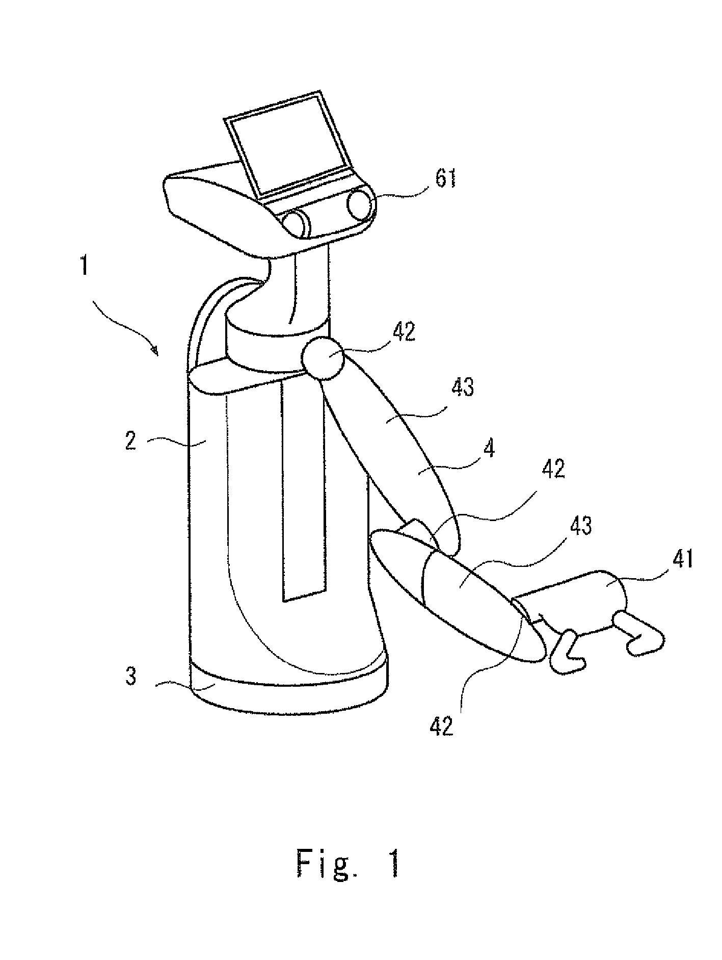
[0023]Hereinafter, with reference to the drawings, embodiments of the present invention will be described. FIG. 1 is an oblique view showing a schematic configuration of a robot according to one embodiment of the present invention. A robot 1 according to this embodiment is configured, for example, as a working robot that performs a remote operation in response to a user's instruction or autonomously performs an operation. A motion limiting device according to this embodiment limits motions of the robot 1.

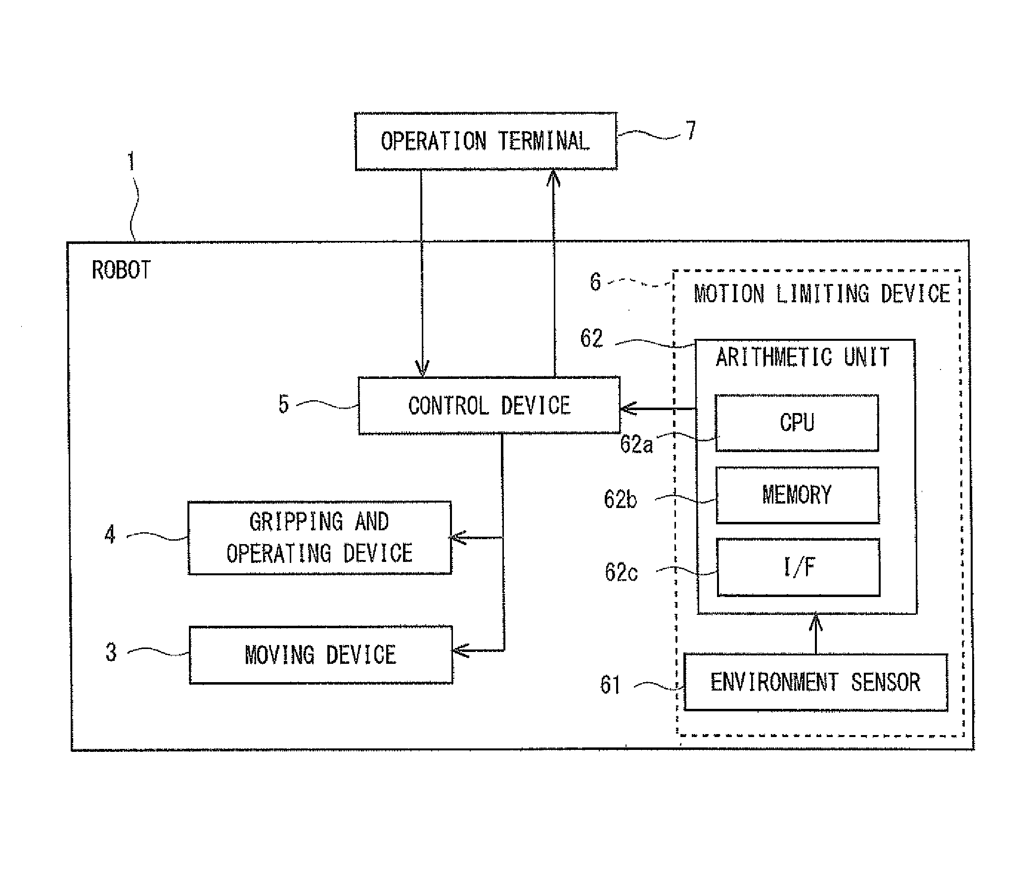
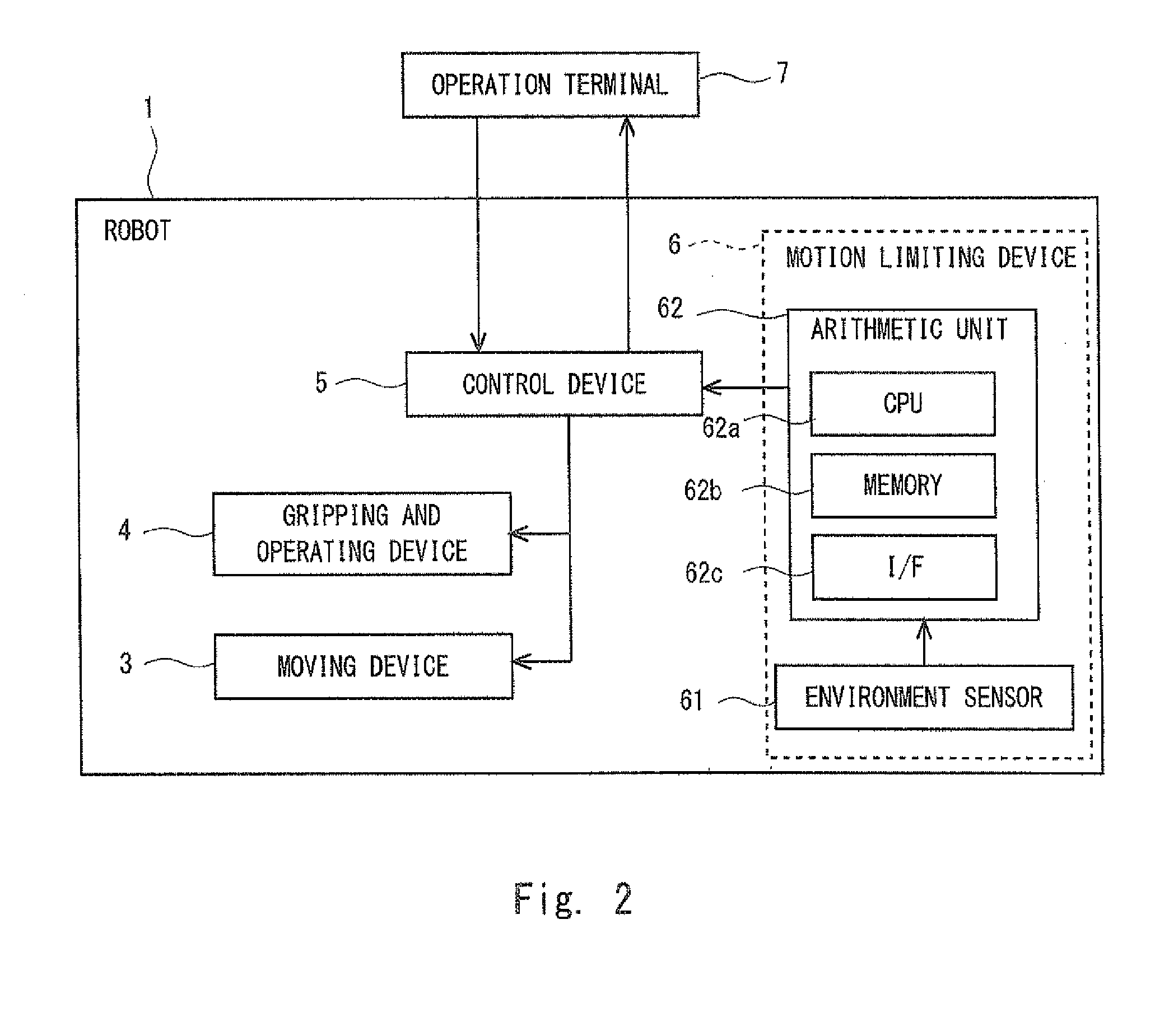
[0024]FIG. 2 is a block diagram showing a schematic system configuration of the robot according to the embodiment of the present invention. The robot 1 according to this embodiment includes a robot body 2, a moving device 3 that moves the robot body 2, a gripping and operating device 4 that holds and moves an object, a control device 5 that controls the moving device 3 and the gripping and operating device 4, and a motion limiting device 6 that limits motions of the moving device 3 ...


PUM


Abstract

A motion limiting device includes: detection means that detects environmental information around a robot; generation means that generates, based on the environmental information detected by the detection means, a three-dimensional environment model that includes an unobservable area and an observable area and indicates a working environment in which the robot operates, the unobservable area being the area where the environmental information cannot be detected by the detection means, and the observable area being the area where the environmental information can be detected by the detection means; and limiting means that limits a motion of the robot when it is determined that the robot has entered the unobservable area based on the three-dimensional environment model generated by the generation means.

Description

INCORPORATION BY REFERENCE[0001]This application is based upon and claims the benefit of priority from Japanese patent application No. 2014-089942, filed on Apr. 24, 2014, the disclosure of which is incorporated herein in its entirety by reference.BACKGROUND OF THE INVENTION[0002]1. Field of the Invention[0003]The present invention relates to a motion limiting device and a motion limiting method that limit motions of a robot.[0004]2. Description of Related Art[0005]A robot is known that determines whether it has come in contact with an obstacle near the robot based on environmental information around the robot and positional information of the robot to avoid the obstacle (see, for example, Japanese Unexamined Patent Application Publication No. 2010-064215).[0006]For example, there may be an unobservable area in which it is impossible for the robot to check for the presence or the absence of an obstacle since the unobservable area is behind the robot itself and it is thus difficult f...

Claims


Application Information

Patent Timeline
Patent Type & Authority Patents(United States)
IPC IPC(8): G05B19/00B25J9/16
CPCB25J9/1666B25J9/162B25J9/1676B25J9/1697G05B2219/40298G05B2219/40323Y10S901/01G05D1/0246G05D2201/0216
Inventor SAITO, FUMINORI
Owner TOYOTA JIDOSHA KK
Why Eureka
Try Eureka