Work vehicle with improved exhaust component cooling

a technology of exhaust components and work vehicles, applied in the field of work vehicles, can solve the problem of requiring a larger space beside the rear half of the engin

Active Publication Date: 2016-10-18
KUBOTA CORP
View PDF12 Cites 2 Cited by
  • Summary
  • Abstract
  • Description
  • Claims
  • Application Information

AI Technical Summary

Benefits of technology

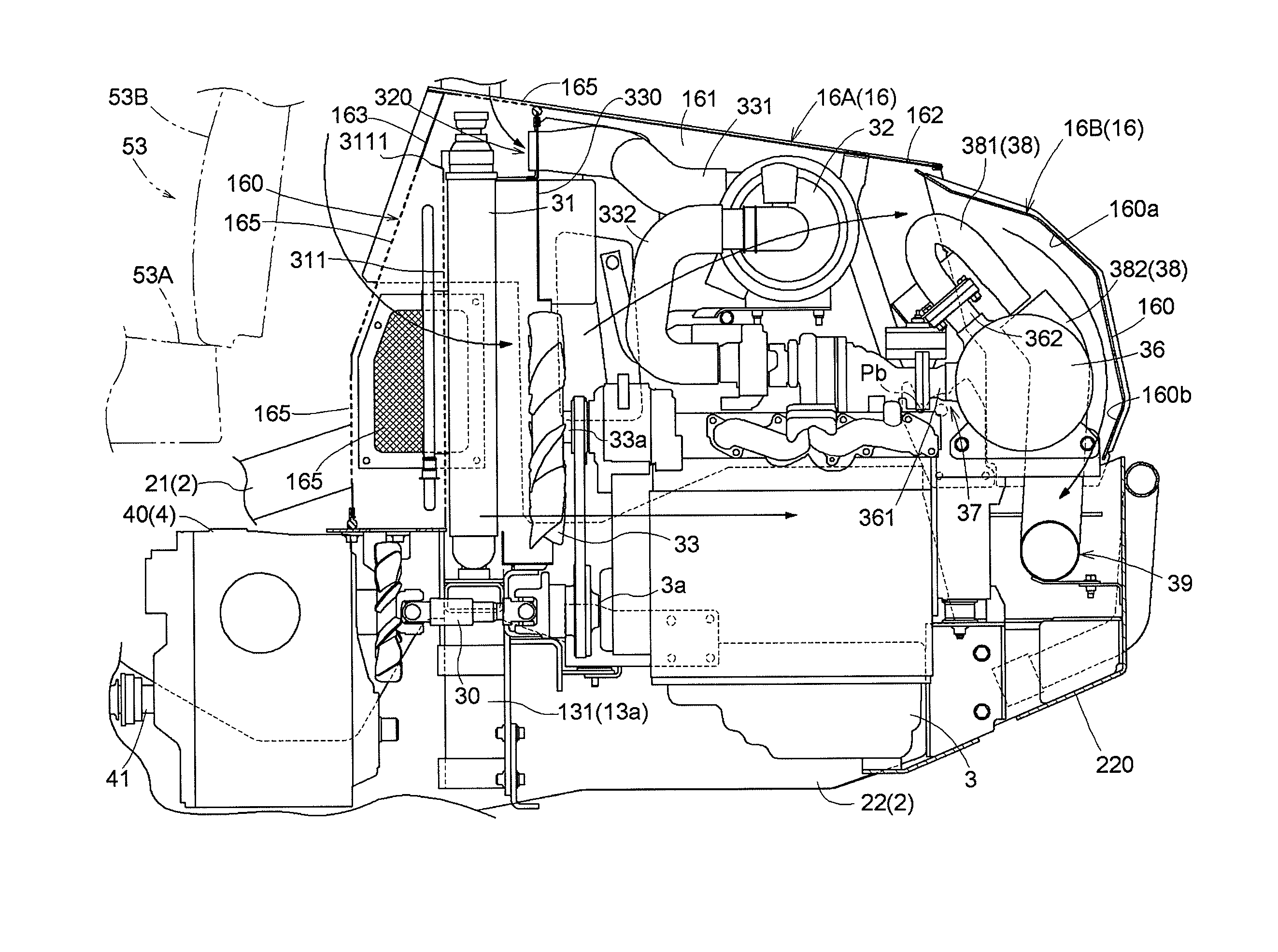
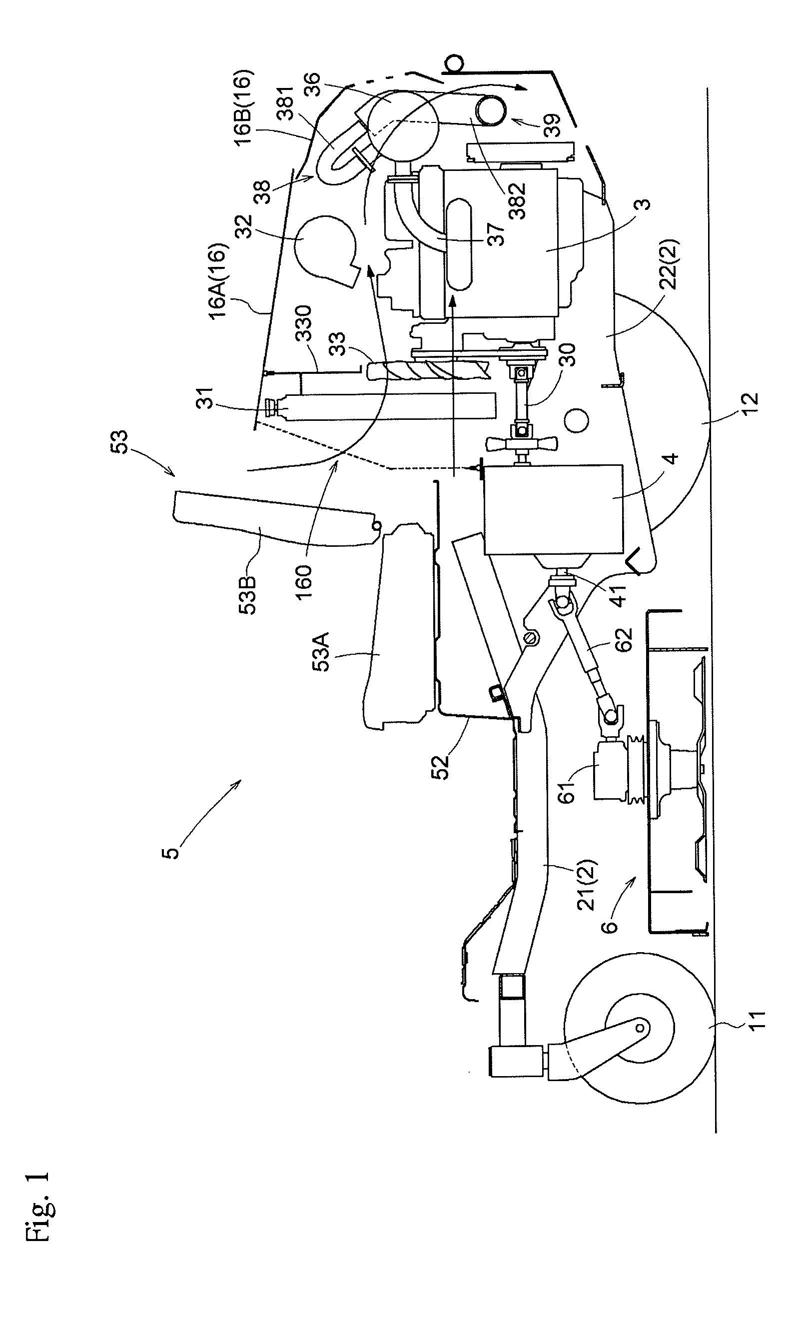
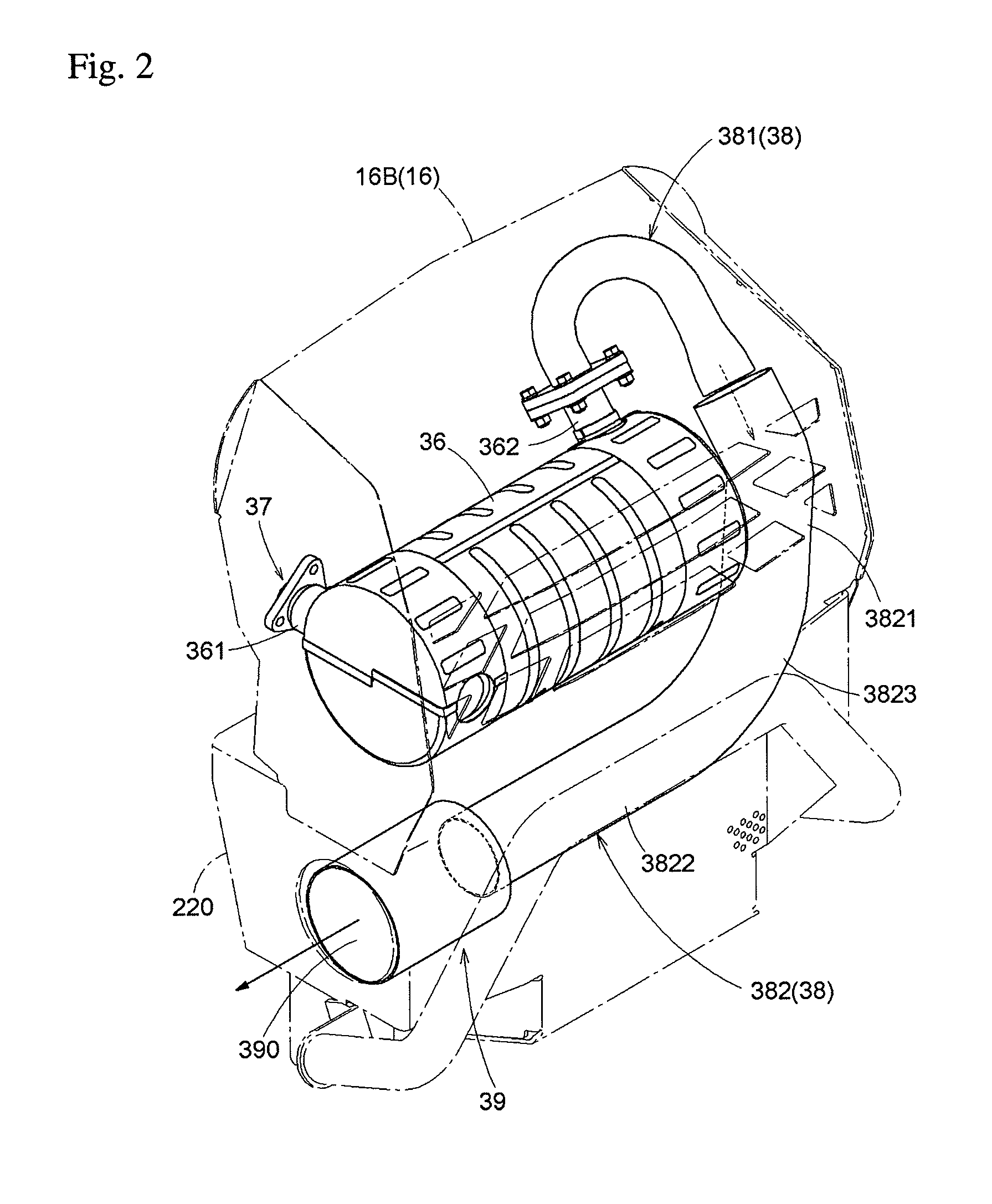
[0010]According to this configuration, the outlet-side exhaust passage, which discharges the exhaust gas exiting the exhaust gas purification device to the exterior while cooling the exhaust gas, rises above the exhaust gas purification device, then reverses course and descends beside the exhaust gas purification device to the bottom end of the exhaust gas purification device, after which the outlet-side exhaust passage extends below the exhaust gas purification device in the transverse direction of the vehicle. Accordingly, a majority of the space above the exhaust gas purification device forms a space where cooling air flows smoothly, and the outlet-side exhaust passage effectively does not occupy areas forward and rearward of the exhaust gas purification device in the front-back direction of the vehicle. In other words, a portion of the cooling air guided into the engine compartment by the cooling fan can pass smoothly above the diesel engine and behind the exhaust gas purification device to reach the outlet-side exhaust passage extending below the exhaust gas purification device in the transverse direction of the vehicle, and the exhaust gas flowing through the outlet-side exhaust passage can be cooled efficiently.
[0012]The second exhaust passage extends beside and below the exhaust gas purification device, where there is extra space, and therefore a sufficiently large flow cross-sectional area can be readily formed. Therefore, in another aspect of the present invention, the flow cross-sectional area of the second exhaust passage is larger than the flow cross-sectional area of the first exhaust passage, and a gap in the transverse direction is formed at the connection between the first exhaust passage and the second exhaust passage such that outside air flows into the second exhaust passage together with exhaust gas from the first exhaust passage.
[0013]The exhaust passage is configured by metal pipes made by sheet metal working; therefore, the simpler the extending shape of the exhaust passage, the lower the manufacturing cost. Thus, in another aspect of the present invention, the second exhaust passage is configured by a downward portion extending downward beside the first end portion of the exhaust gas purification device; a sideways portion extending horizontally in a straight line below the exhaust gas purification device; and a two-dimensional bend portion coupling the downward portion and the sideways portion (having a center line of the bend positioned substantially on a two dimensional plane).
[0016]High temperatures are generated in the exhaust gas purification device while being renewed, and therefore hot air in the vicinity of the exhaust gas purification device must be pushed away. Therefore, in another aspect of the present invention, the radiator is arranged such that a height-direction center portion of the radiator, which is positioned forward of the diesel engine, is in a boundary region situated between the diesel engine and the air cleaner, which is positioned above the diesel engine. A lower half of the flow of air passing the radiator and entering the engine compartment cools a surface of the engine while directly striking the diesel engine, and an upper half of the flow of air pushes hot air rising above the diesel engine away to lower a temperature within the engine compartment. According to this configuration, cooling of the diesel engine itself, as well as outflow of hot air above the engine and in the vicinity of the exhaust gas purification device, is achieved efficiently.

Problems solved by technology

In particular, a flow cross-sectional area of the exhaust pipe close to the exhaust outlet is large, and therefore the required space beside the rear half of the engine is larger.

Method used


Image

  • Work vehicle with improved exhaust component cooling
  • Work vehicle with improved exhaust component cooling
  • Work vehicle with improved exhaust component cooling

Examples


Embodiment Construction

[0028]The particulars shown herein are by way of example and for purposes of illustrative discussion of the embodiments of the present invention only and are presented in the cause of providing what is believed to be the most useful and readily understood description of the principles and conceptual aspects of the present invention. In this regard, no attempt is made to show structural details of the present invention in more detail than is necessary for the fundamental understanding of the present invention, the description taken with the drawings making apparent to those skilled in the art how the forms of the present invention may be embodied in practice.

[0029]Before describing a specific embodiment of a mower according to the present invention in which a diesel engine (hereafter referred to simply as an engine) is mounted, a basic structure of the present invention is described with reference to FIGS. 1 and 2. A mower is shown in FIG. 1 as an exemplary work vehicle according to ...


PUM


Abstract

A work vehicle in which a cooling fan is arranged forward of an engine and an exhaust gas purification device is arranged rearward of the engine. An inlet-side exhaust passage connects an exhaust manifold and the exhaust gas purification device. An outlet-side exhaust passage connects the exhaust gas purification device and the exhaust end portion. A first exhaust passage is coupled to the exhaust gas purification device and passes over the exhaust gas purification device to reach beside a first end portion. A second exhaust passage is coupled to the first exhaust passage and extends in a transverse direction and below the exhaust gas purification device.

Description

CROSS-REFERENCE TO RELATED APPLICATIONS[0001]The present application claims priority under 35 U.S.C. §119 of Japanese Application No. 2015-000360, filed on Jan. 5, 2015, the disclosure of which is expressly incorporated by reference herein in its entirety.BACKGROUND OF THE INVENTION[0002]1. Field of the Invention[0003]The present invention relates to a work vehicle having a diesel engine installed in a rear portion of a vehicle frame. The vehicle has a system that improves exhaust component cooling.[0004]2. Description of Related Art[0005]In order to improve and resolve the environmental concerns of recent years, exhaust gas regulations have been toughened for diesel engines and the like. In work vehicles such as construction or agricultural machinery, various technologies have been developed which reduce particulate matter contained in exhaust gas so as to comply with such exhaust gas regulations. For example, instead of a conventional muffler, an exhaust gas purification device co...

Claims


Application Information

Patent Timeline
Patent Type & Authority Patents(United States)
IPC IPC(8): B60K13/04F01N13/14F01N13/18F01N3/05F01N3/021B60K11/06
CPCB60K13/04B60K11/06F01N3/021F01N3/055F01N13/143F01N13/1805F01N2260/022B60Y2200/223Y02T10/12
Inventor MINOURA, AKIRANOGAMI, KAZUAKISHIRAGA, TAKAHIROUMEMOTO, HIDEYA
Owner KUBOTA CORP
Why Eureka
Try Eureka