Combustion chamber

a combustion chamber and combustion chamber technology, applied in combustion chambers, indirect carbon-dioxide mitigation, combustion processes, etc., can solve the problems of poor combustion air entering the combustion chamber, achieve the effect of improving the efficiency of the turbine, enhancing the burning of fuel, and reducing the emission of flue gas

Active Publication Date: 2016-10-18
RMV TECH
View PDF13 Cites 0 Cited by
  • Summary
  • Abstract
  • Description
  • Claims
  • Application Information

AI Technical Summary

Benefits of technology

[0005]This structure provides a strong vortical inflow of combustion air into the annular channel and therefrom further to the flame tube, wherein the vortical flow continues. This improves and enhances the burning of the fuel fed to the flame tube. Simultaneously, it is possible to significantly improve the efficiency of a turbine typically associated with the combustion chamber and reduce flue gas emissions. Owing to the shaped flow apertures of the flame tube, the combustion air moves efficiently inside the flame tube while at the same time the vorticity of the combustion air remains or further increases, efficiently mixing up the combustion air and the fuel. Conventionally, these flow apertures or discharge channels have simply been mere holes cut in the casing of the flame tube.
[0006]Preferably, the flow apertures of the cover part are separated from one another by flow control wings located obliquely with respect to the longitudinal axis of the combustion chamber. These control wings enable the inflow of combustion air to be fine-adjusted as desired.

Problems solved by technology

The problem with the prior art combustion chamber is that with respect to flow technology, the feed of combustion air into the chamber is not very good.

Method used


Image

  • Combustion chamber
  • Combustion chamber
  • Combustion chamber

Examples


Embodiment Construction

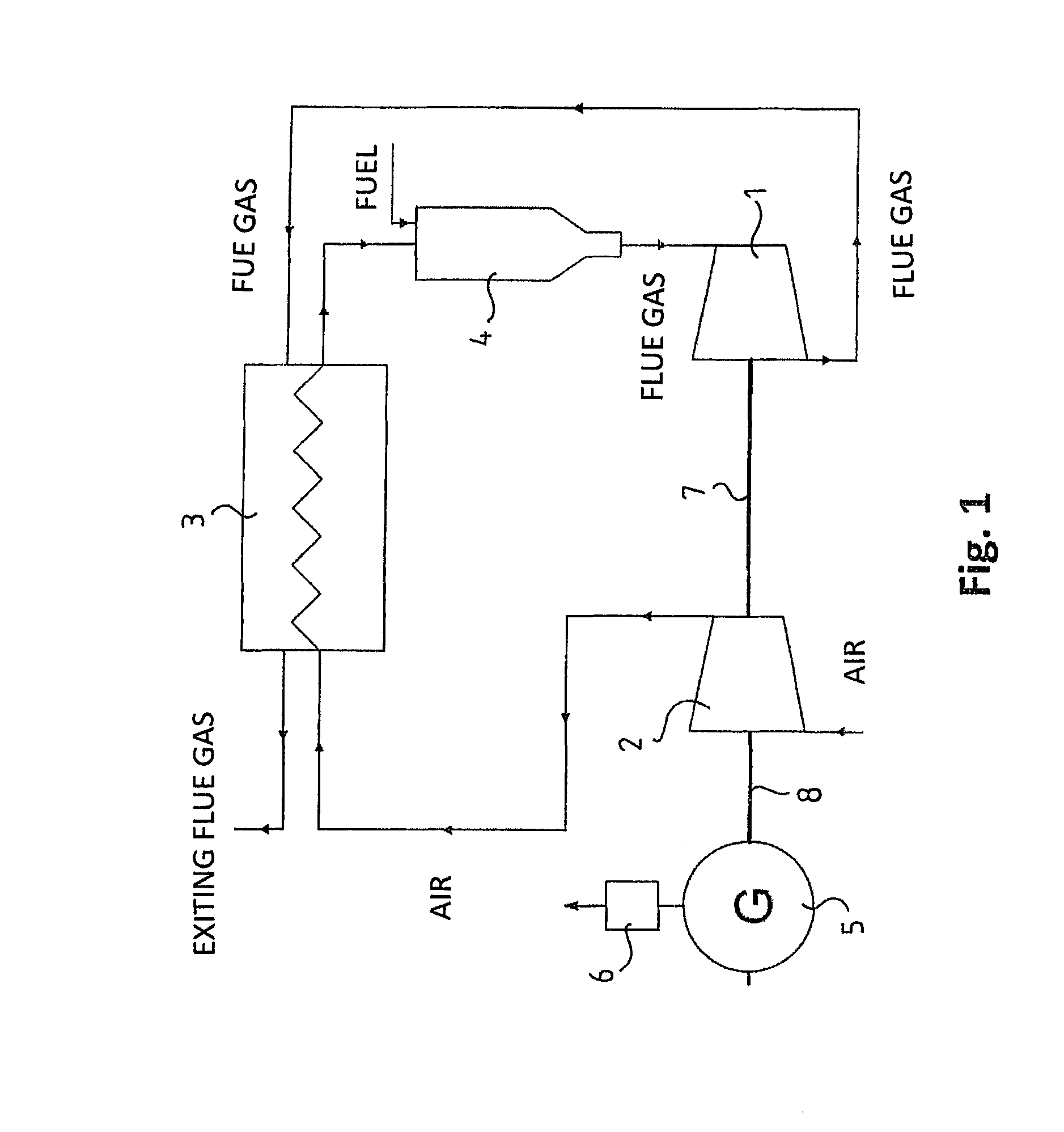
[0012]FIG. 1 schematically shows a gas turbine system for producing electric energy, the combustion chamber according to the invention being particularly suitable for the system. As its main components, this system comprises a turbine 1, a compressor 2, a heat exchanger 3, a combustion chamber 4, a generator 5, and a frequency converter 6.

[0013]A runner wheel of the turbine 1 and the compressor 2 are connected to the same shaft 7, and the generator 5 is connected by an intermediate shaft 8 to an entity formed by the turbine 1 and the compressor 2. The compressor 2 compresses inlet air it has taken and blows the compressed air to the heat exchanger 3 to be pre-heated. The pre-heated air is conveyed to the combustion chamber 4, whereto fuel is also fed. A mixture of air and fuel burns in a flame tube located inside the combustion chamber 4 and advances therefrom as a flue gas flowing at a high speed, rotating the runner wheel of the turbine 1. The runner wheel of the turbine 1, in tur...


PUM


Abstract

The invention relates to a combustion chamber for burning an air-fuel mixture, a gas mixture or a gas-liquid mixture, including an outer casing; a flame tube located inside the outer casing and provided with an inner space, whereby the outer casing and the flame tube form an annular channel therebetween, the flame tube including flow apertures which penetrate through its casing and interconnect the annular channel and the inner space of the flame tube; a cover part arranged in inlet ends of the outer casing and the flame tube and provided with flow apertures opening up into the annular channel; a combustion air inlet part which is arranged in an outer surface of the cover part and which is in connection with the flow apertures of the cover part; a fuel jet located in the cover part and extending inside the flame tube for feeding fuel into the flame tube.

Description

BACKGROUND OF THE INVENTION[0001]The invention relates to a combustion chamber for burning an air-fuel mixture, a gas mixture or a gas-liquid mixture, comprising an outer casing provided with an inner space, an inlet end and an outlet end, whereby the inner space tapers towards the outlet end over a determined section of the length of the casing; a flame tube located in the inner space of the outer casing and provided with an inner space, an inlet end and an outlet end on sides corresponding to those of the inlet end and the outlet end of the outer casing, whereby the flame tube tapers towards its outlet end over a determined section of the length of the flame tube, and whereby an inner surface of the outer casing and an outer surface of the flame tube form an annular channel therebetween, the flame tube comprising flow apertures which penetrate through its casing and interconnect the annular channel and the inner space of the flame tube; a cover part arranged in the inlet ends of t...

Claims


Application Information

Patent Timeline
Patent Type & Authority Patents(United States)
IPC IPC(8): F23R3/12F23R3/06F23L15/00F23R3/28F23C3/00F23R3/44F23R3/58
CPCF23R3/12F23C3/006F23L15/00F23R3/06F23R3/28F23R3/44F23R3/58F23R2900/03043Y02E20/34F23C7/002
Inventor VIITAMAKI, MARKUS
Owner RMV TECH
Why Eureka
Try Eureka