Liquid ejection head and manufacturing method of liquid ejection head

a technology of liquid ejection head and manufacturing method, which is applied in printing and other directions, can solve the problems of low ejection port forming member, difficult to make the temperature of ink highly stable, and inability to select ink, etc., and achieves high environmental reliability

Active Publication Date: 2016-10-25
CANON KK
View PDF24 Cites 5 Cited by
  • Summary
  • Abstract
  • Description
  • Claims
  • Application Information

AI Technical Summary

Benefits of technology

[0009]Thus, the present invention provides, in a liquid ejection head having a printing element substrate in which an ejection port forming member is formed on a Si substrate, a liquid ejection head which suppresses a crack of the Si substrate and peeling-off of the ejection port forming member and has high environmental reliability and a manufacturing method of a liquid ejection head.
[0011]According to the present invention, a liquid ejection head which suppresses a crack of the Si substrate and peeling-off of the ejection port forming member and has high environmental reliability can be realized.

Problems solved by technology

In order to eject high-viscous ink, it is usually necessary to warm the ink so as to lower the viscosity, but with the support member using alumina, the warmed ink easily cools, and it has been difficult to make the temperature of the ink highly stable before ejection in advance.
That is, with the conventional liquid ejection head using alumina for the support member, ink that can be selected is limited.
That is, due to a synergic effect of the residual stress of the Si substrate and expansion and contraction of each of the Si substrate and the support member caused by a temperature change in use of the liquid ejection head based on a difference in the linear expansion coefficient between them, the Si substrate might be cracked or the ejection port forming member might be peeled off the Si substrate.

Method used


Image

  • Liquid ejection head and manufacturing method of liquid ejection head
  • Liquid ejection head and manufacturing method of liquid ejection head
  • Liquid ejection head and manufacturing method of liquid ejection head

Examples


first embodiment

[0029]A first embodiment of the present invention will be described below by referring to the attached drawings.

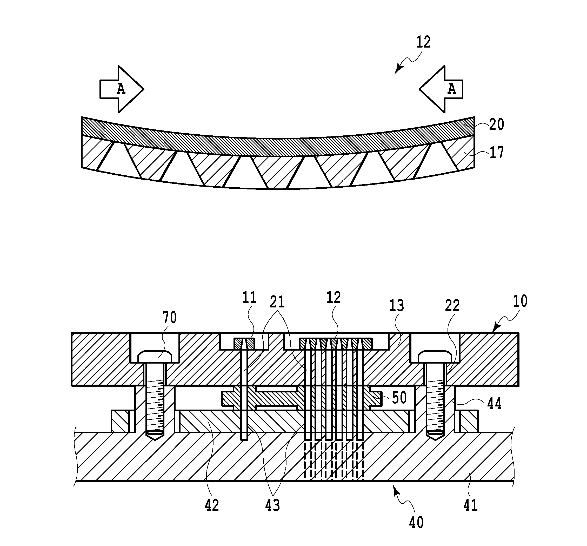
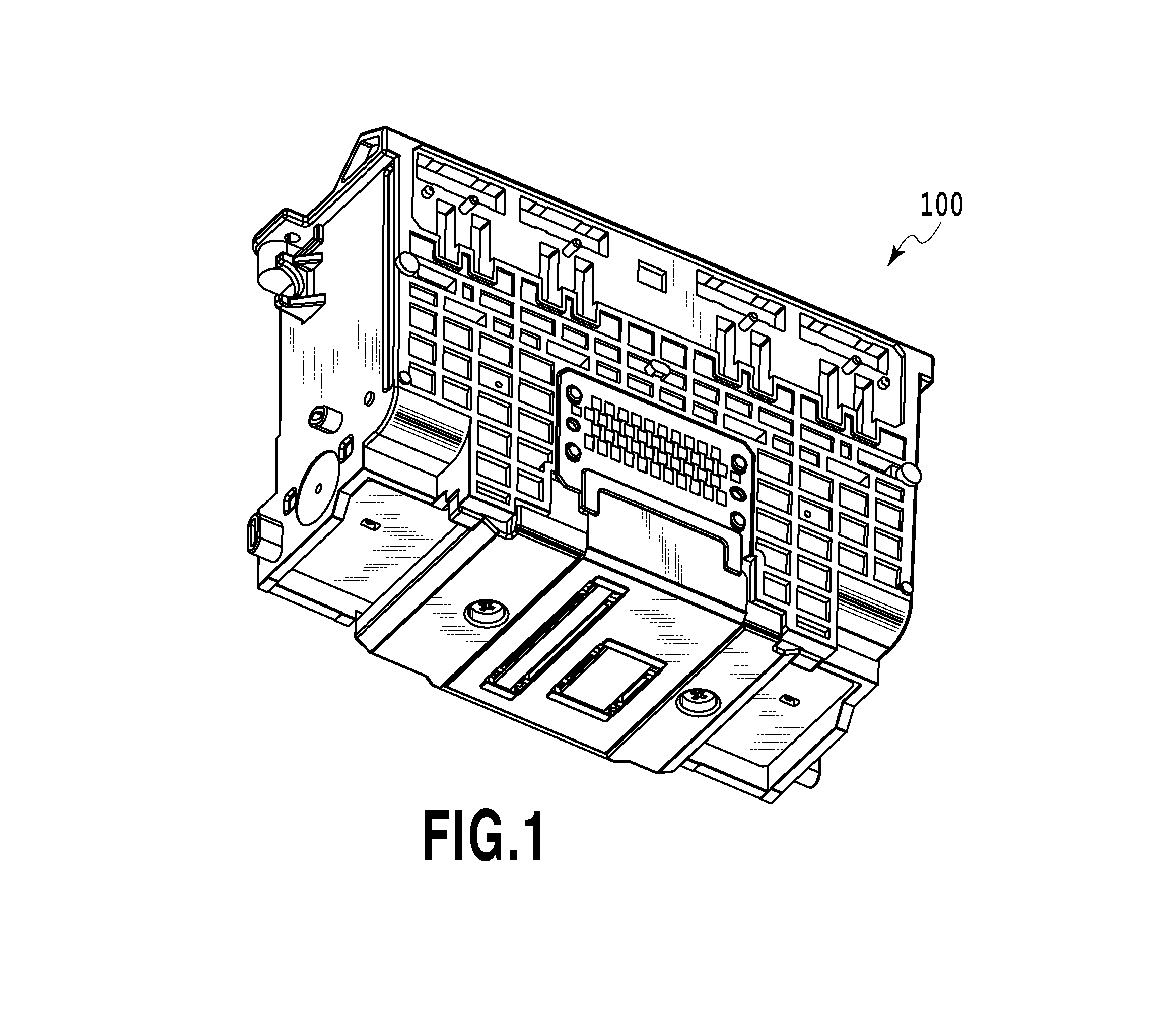
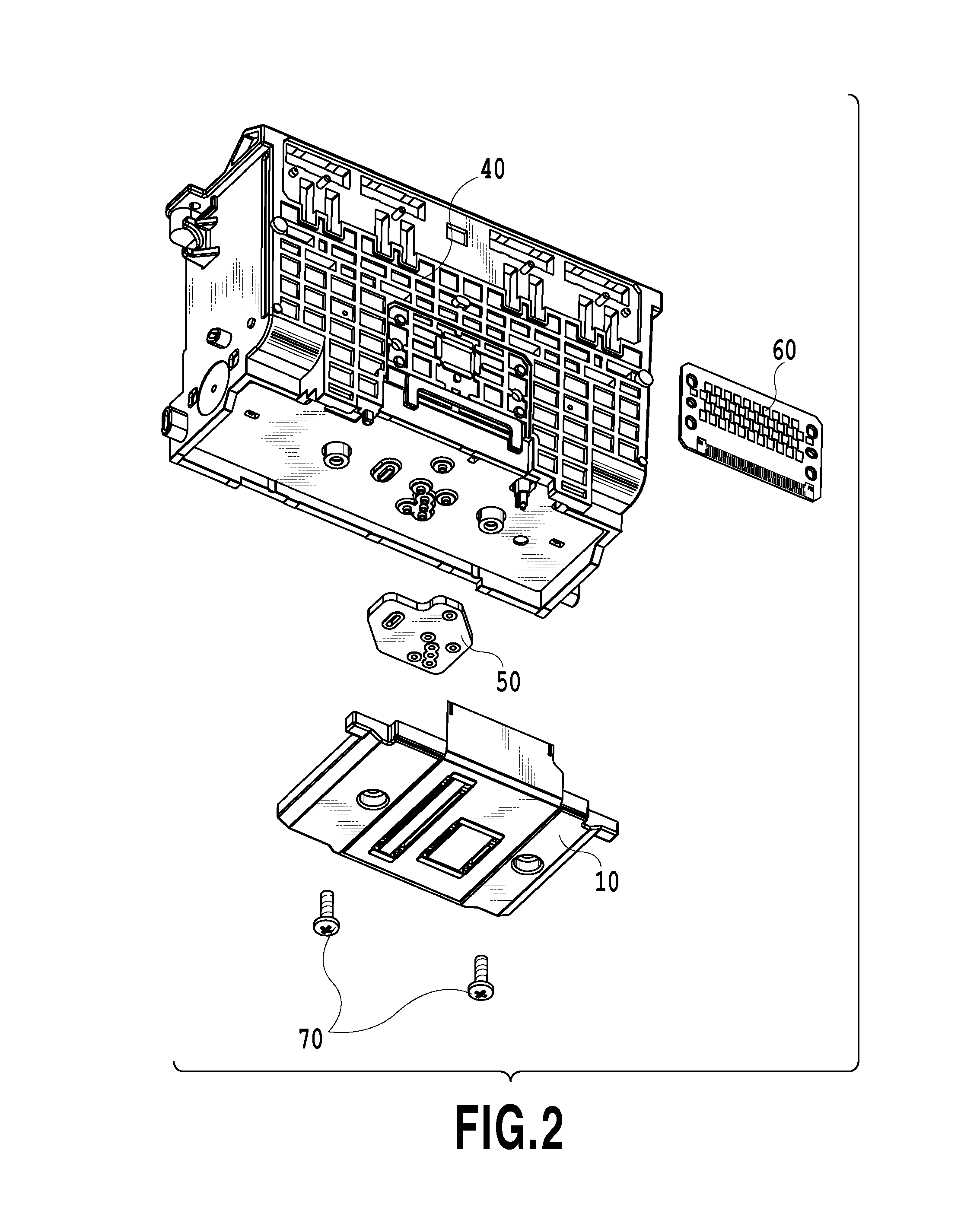
[0030]FIG. 1 is a schematic diagram illustrating a liquid ejection head of the first embodiment, and FIGS. 2 and 3 are exploded views of the liquid ejection head. A liquid ejection head 100 has a printing element unit 10, a channel unit 40, an elastic member 50, an electric substrate 60, and a screw 70. The printing element unit 10 has printing element substrates 11 and 12, a plate-shaped support member (first support member) 13, and an electric wiring substrate 14, and the channel unit 40 (second support member) has a housing 41 and a channel plate 42.

[0031]The channel unit 40 has the channel plate 42 bonded and fixed to the housing 41 by ultrasonic welding so as to form a liquid supply path for leading a liquid from an ink tank (not shown) for storage to a liquid inlet. The housing 41 and the channel plate 42 are formed of a resin such as a modified polyphenylene ether r...

second embodiment

[0043]A second embodiment of the present invention will be described below by referring to the attached drawings. Since the basic configuration of this embodiment is similar to that of the first embodiment, only a characteristic configuration will be described below.

[0044]FIG. 10 is a view for explaining a printing element unit of the second embodiment. Since the configurations other than the printing element unit are the same as those of the liquid ejection head of the first embodiment, explanation will be omitted. In the support member 13, a concave portion 23 for accommodating the printing element substrates 11 and 12 in the thickness direction of the support member 13 is provided. Outer peripheries (or at least a part thereof) of the printing element substrates 11 and 12 bonded and fixed to the concave portion 23 of the support member 13 are sealed by a sealing material 24. Since the support member 13 is formed of a resin, the concave portion 23 can be provided easily. By sealin...


PUM

PropertyMeasurementUnit
widthaaaaaaaaaa
widthaaaaaaaaaa
thicknessaaaaaaaaaa

Abstract

A liquid ejection head with high environmental reliability which suppresses a crack of a Si substrate and peeling-off of an ejection port forming member by relaxing a residual stress in a printing element substrate and a manufacturing method of a liquid ejection head are provided. For that purpose, after the printing element substrate is bonded and fixed to a support member, the support member is screwed and fixed through an elastic member.

Description

BACKGROUND OF THE INVENTION[0001]1. Field of the Invention[0002]The present invention relates to a liquid ejection head mounted on a liquid ejecting device performing a print operation by ejecting a printing liquid such as ink and a manufacturing method of a liquid ejection head.[0003]2. Description of the Related Art[0004]Japanese Patent Laid-Open No. 2002-19146 discloses a liquid ejection head in which a joint seal member is sandwiched between a channel unit formed with a liquid supply path and a support member supporting a printing element substrate and they are press-contacted with each other by a screw to be joined so that the liquid may not leak. The printing element substrate is formed of a silicon (Si) wafer, and a material of the support member uses alumina, e.g., having a linear expansion coefficient equal to that of the printing element substrate.[0005]By making the linear expansion coefficients of the printing element substrate and the support member equal, a stress appl...

Claims


Application Information

Patent Timeline
Patent Type & Authority Patents(United States)
IPC IPC(8): B41J2/015B41J2/14B41J2/16
CPCB41J2/14B41J2/16B41J2/1623B41J2/1626B41J2/1635B41J2002/14362Y10T29/49403
Inventor KUDO, KIYOMITSUKIMURA, SATOSHIKURODA, TOMOTSUGUTSUJIUCHI, NAOKO
Owner CANON KK
Why Eureka
Try Eureka