
Rolling bearing

a technology of rolling bearings and oil, which is applied in the direction of roller bearings, mechanical devices, transmissions, etc., can solve the problems of reducing the durability of rolling bearings, affecting the service life of rolling bearings, and containing a large amount of foreign substances inside the casing of power transmission devices such as differentials and reduction gears, so as to prolong the service life and improve the strength and reliability of sealing rings. , the effect of not easily deformed

Active Publication Date: 2016-10-25
NTN CORP
View PDF19 Cites 2 Cited by
  • Summary
  • Abstract
  • Description
  • Claims
  • Application Information

AI Technical Summary

Benefits of technology

The present invention relates to a rolling bearing with an improved sealing ring that has oil flow holes with filters. The sealing ring has weld lines in the areas where no oil flow holes are present to increase its strength and reliability. The sealing ring is made of a material harder than the annular member, preventing foreign substances from entering through gaps. The filters can be securely fixed to the sealing ring, and the annular member can be replaced without replacing the sealing ring, prolonging the life of the sealing member and the bearing.

Problems solved by technology

However, the oil filled inside the casings of the power transmission devices such as transmissions, differentials and reduction gears contains relatively large amount of foreign substances, such as gear wear debris (iron dust and the like).
If the foreign substances contained in the oil get inside the rolling bearing, the foreign substances between the raceway surfaces of the rolling bearing and the rolling contact surfaces of the rolling elements in the bearing could cause peeling on these surfaces, thereby resulting in a decrease in the durability of the rolling bearing.

Method used


Image

  • Rolling bearing
  • Rolling bearing
  • Rolling bearing

Examples


Embodiment Construction

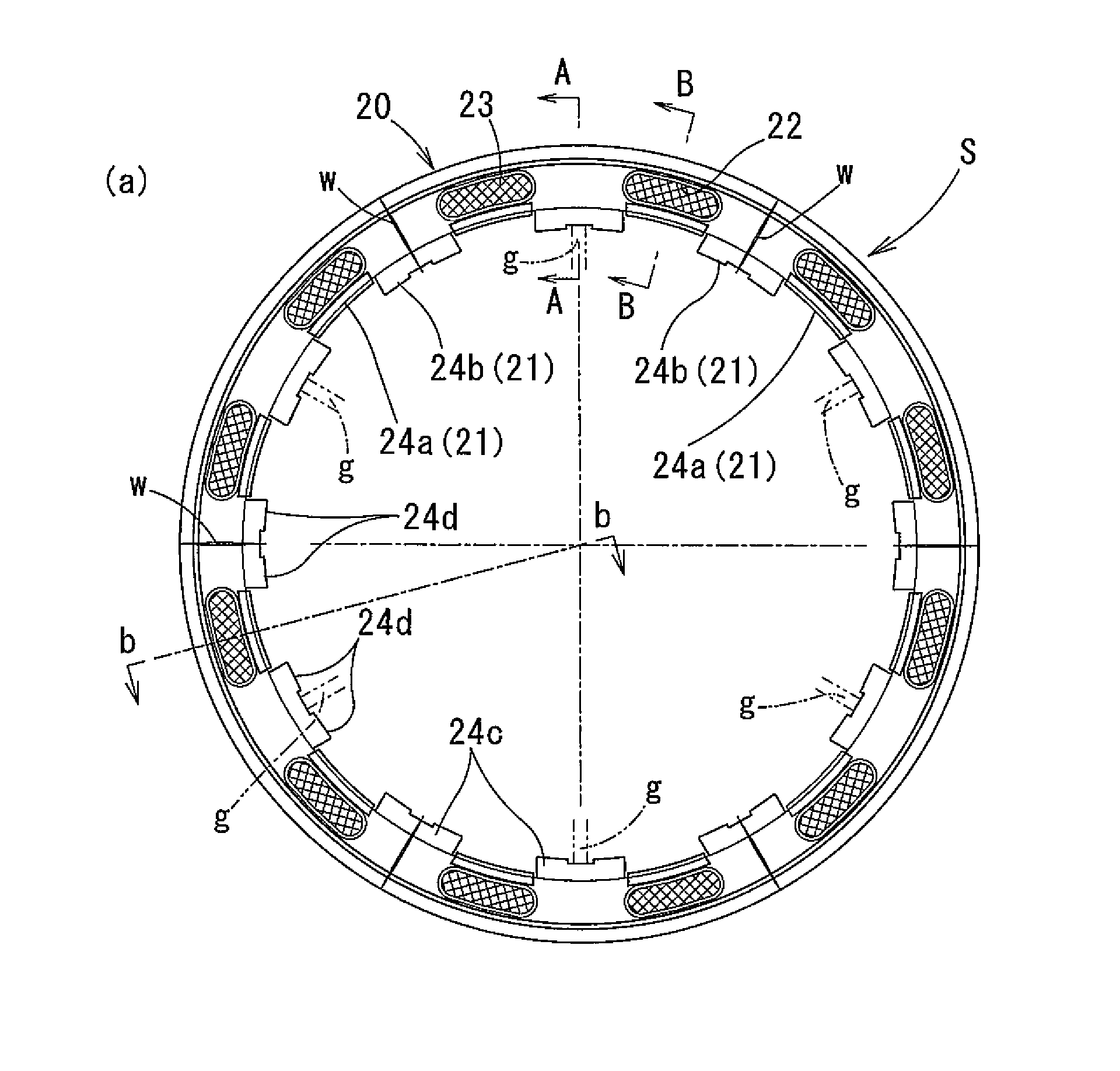
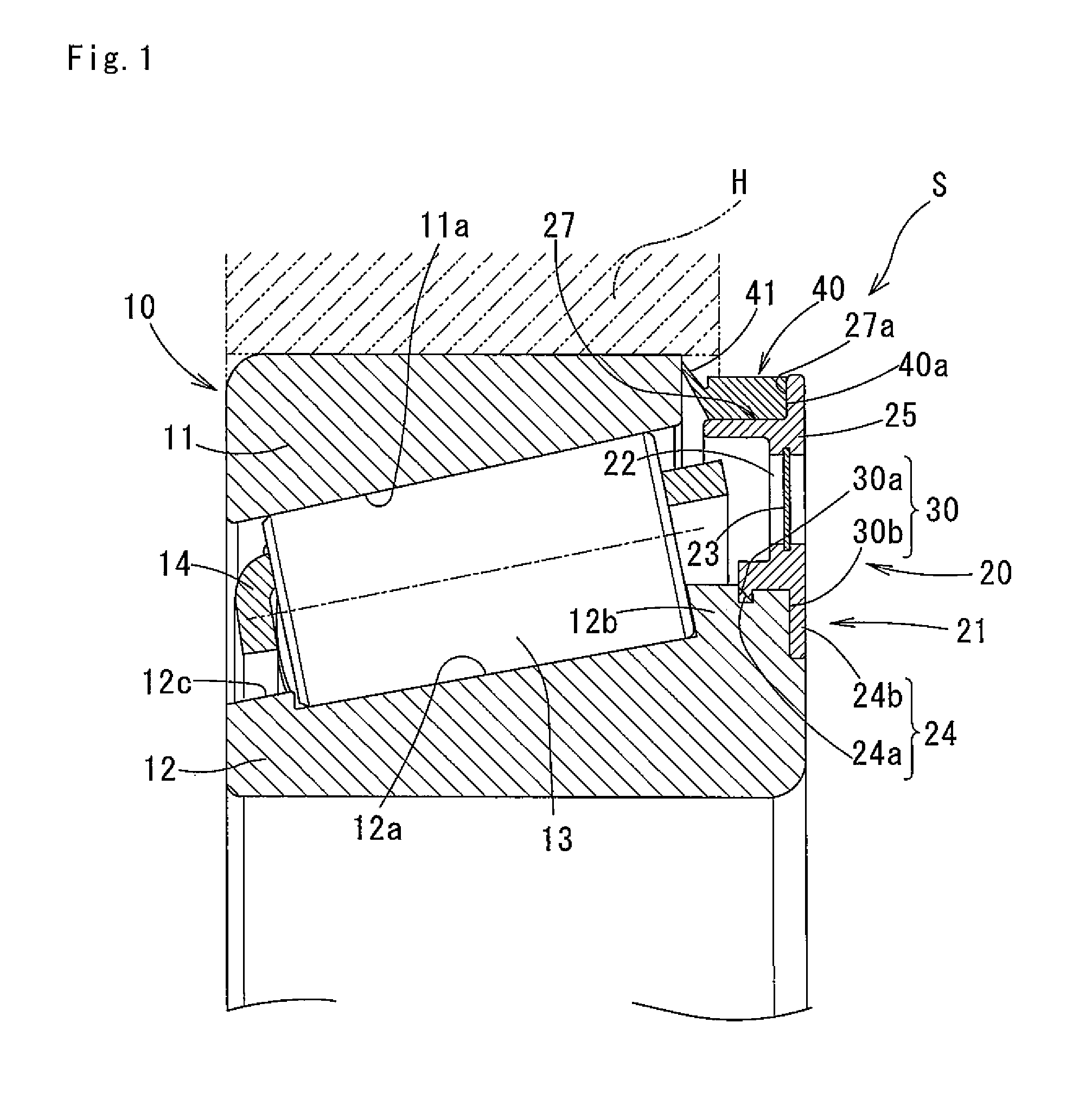
[0062]The embodiments of the present invention will now be described with reference to the drawings. A rolling bearing 10 according to the embodiment of the present invention is a tapered roller bearing. The rolling bearing 10 includes, as shown in FIG. 1, an outer race 11, an inner race 12, and tapered rollers as rolling elements 13 received between the raceway surface 11a of the outer race 11 and the raceway surface 12a of the inner race 12. The positions of the rolling elements 13 in the circumferential direction are retained by a retainer 14.

[0063]In the present embodiment, the inner race 12 is designed to be a fixed side, capable of being fixed to an shaft, and the outer race 11 is designed to be a rotating side configured to rotate together with a housing H. However, a reversed embodiment is also possible in which the inner race 12 is designed to be the rotating side and the outer race 11 is designed to be the fixed side.

[0064]A sealing member S is attached to the rolling bear...


PUM

PropertyMeasurementUnit
shrinkage ratioaaaaaaaaaa
sizeaaaaaaaaaa

Abstract

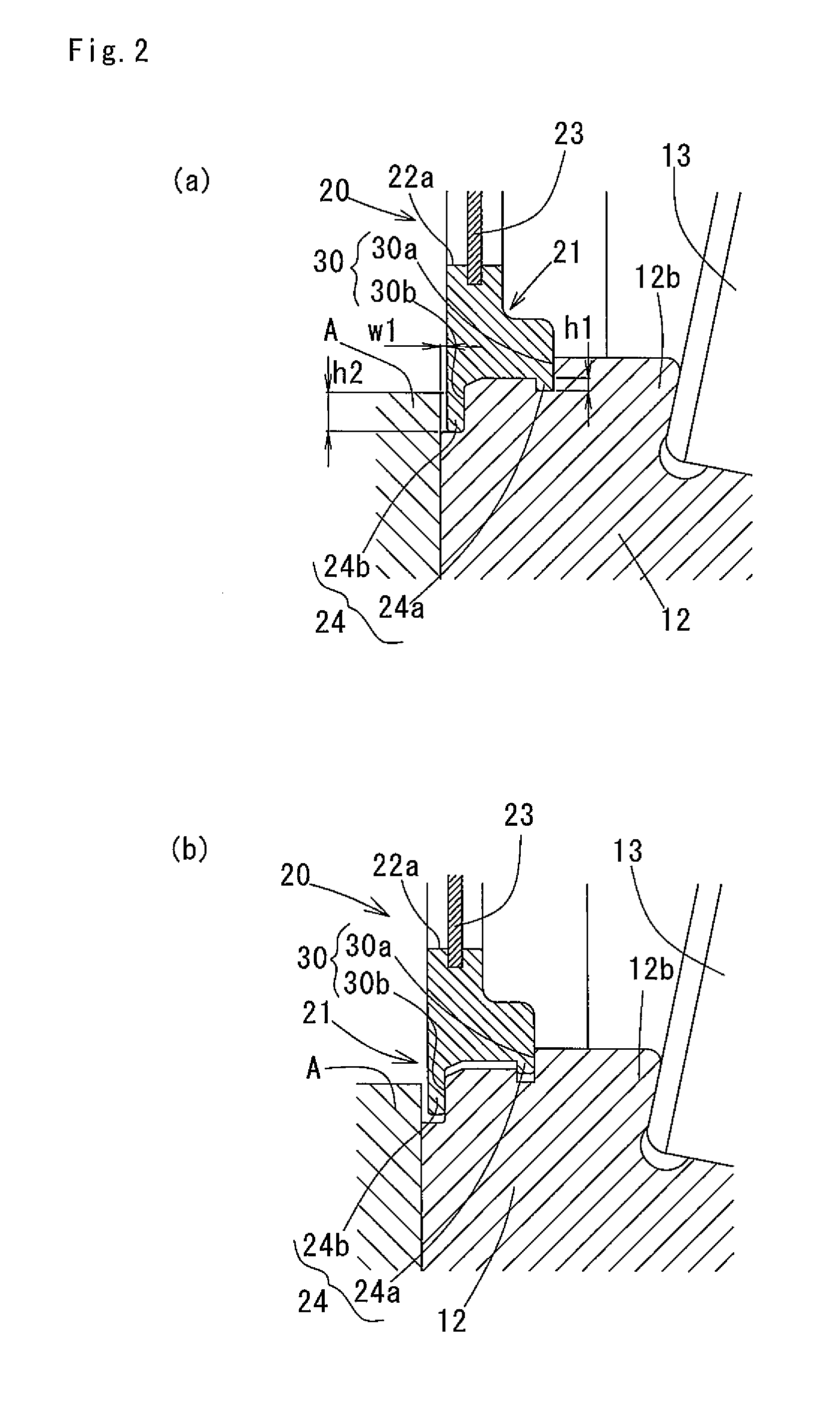
A rolling bearing is provided wherein one open end of a bearing space formed between an outer race and an inner race is covered with a sealing ring provided with oil flow holes provided with filters. The sealing ring includes engaging portions provided on the sealing ring in a protruding manner along a circumferential direction thereof, and engaged in recesses provided on the inner race. An annular member made of a material softer than that of the sealing ring is fixed to the sealing ring. The annular member includes a lip portion facing the outer race with a gap or kept in contact with the outer race. The sealing ring is formed by injection molding a resin, and weld lines generated during the injection molding are formed in portions of the sealing ring corresponding to radial directions along which the oil flow holes are not disposed.

Description

BACKGROUND OF THE INVENTION[0001]1. Field of the Invention[0002]The present invention relates to a rolling bearing lubricated with oil. More specifically, the present invention relates to a rolling bearing lubricated with oil which is filtered through filters.[0003]2. Description of Related Art[0004]Power transmission devices such as transmissions, differentials and reduction gears in automobiles and various types of construction machines, or travel units including these devices, include rolling bearings.[0005]Some of these types of travel units have a structure in which rolling bearings are lubricated with the same oil used to lubricate the power transmission devices.[0006]However, the oil filled inside the casings of the power transmission devices such as transmissions, differentials and reduction gears contains relatively large amount of foreign substances, such as gear wear debris (iron dust and the like). If the foreign substances contained in the oil get inside the rolling bea...

Claims


Application Information

Patent Timeline
Patent Type & Authority Patents(United States)
IPC IPC(8): F16C33/66F16J15/32F16C33/76F16C33/58F16C19/26F16C33/78F16C43/06F16C33/72B29C45/00F16C43/04F16C19/36B29L31/26
CPCF16C33/586B29C45/0025F16C19/26F16C33/667F16C33/783F16C33/7816F16C33/7833F16C33/7889F16C43/06B29C2045/0034B29L2031/26F16C19/364F16C33/726F16C33/7886F16C43/045Y10T29/49684F16C33/7813
Inventor SHIMIZU, YASUHIROYAMAUCHI, KIYOSHIGEYAMAMOTO, NAOTAMIYAZAKI, HIROYUKI
Owner NTN CORP
Learn More