Supercharge Your Innovation With Domain-Expert AI Agents!

Window member for display screen of portable terminal and method for fabricating the window member

a portable terminal and window member technology, applied in the field of electronic devices, can solve the problems of high cost, high processing cost, and high cost of the surface of reinforced glass, and achieve the effects of reducing yield, reducing production cost, and reducing production cos

Active Publication Date: 2016-10-25
SAMSUNG ELECTRONICS CO LTD
View PDF19 Cites 0 Cited by
  • Summary
  • Abstract
  • Description
  • Claims
  • Application Information

AI Technical Summary

Benefits of technology

The patent describes a window member that has a uniform density distribution and is made through injection molding. This process prevents the window from shrinking during hardening. The method for making the window member is also provided.

Problems solved by technology

However, to minimize screen distortion, much time and cost are expended for processing the surface of the reinforced glass.
Moreover, generation of a defect due to chips in the glass during processing lowers yield.
Moreover, if the gate is disposed in the center of the mold for molding the window member, the screen is likely to be distorted.
However, since the window 10 is formed using only one melt-resin gate (not shown) disposed slantly toward a side of the mold, when the window is molded to have the curved surface, sufficient pressure is not delivered to the melt resin in a position far away from the gate, i.e., at the left end portion of window 10.
As a result, the density of the window member is not uniform during hardening of the injected melt resin, or the injection-molded product shrinks in its portion to which the pressure for injecting the melt resin is not sufficiently delivered.
These problems can cause deviation of the density or thickness distribution of the window member from a design requirement, eventually distorting the screen displayed through the display device.

Method used


Image

  • Window member for display screen of portable terminal and method for fabricating the window member
  • Window member for display screen of portable terminal and method for fabricating the window member
  • Window member for display screen of portable terminal and method for fabricating the window member

Examples


Embodiment Construction

[0021]Hereinafter, exemplary embodiments of the present invention will be described in detail with reference to the accompanying drawings. The detailed descriptions of functions and configurations incorporated herein that are well known to those skilled in the art will be omitted to avoid unnecessarily obscuring the present invention.

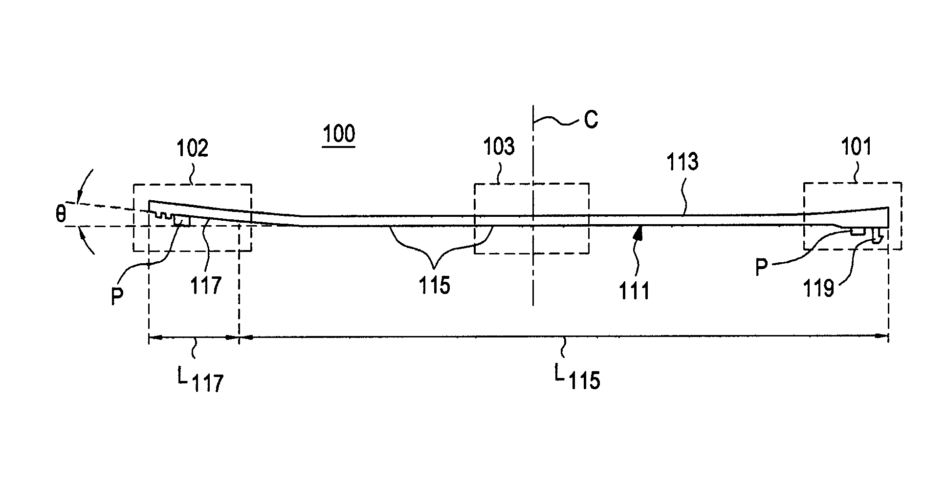
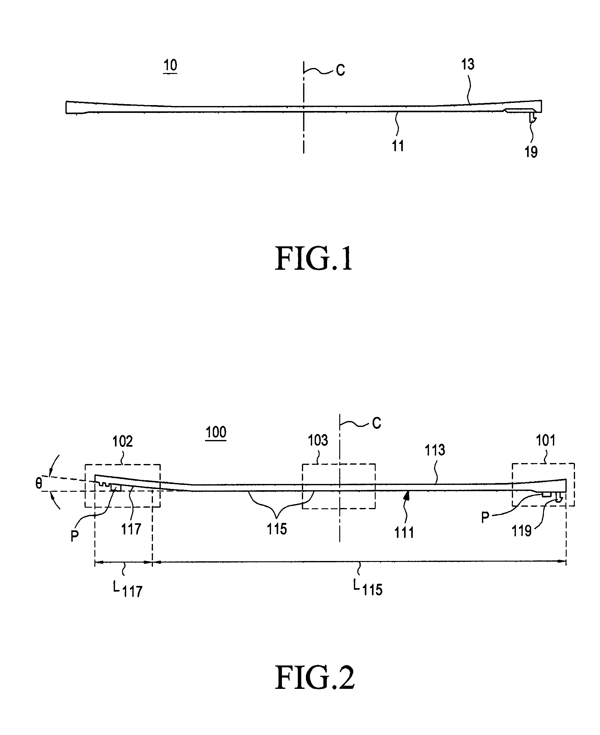
[0022]FIG. 2 is a side view of an embodiment of a window member (“window”) in accordance with the invention, designated as 100. Window 100 has an outer surface 113 formed as a curved surface, and an inner surface 111 comprised of inner surface portions 115 and 117. Surface portion 115 is generally flat, and extends a distance L115 along the length of the window 100. Surface portion 117 is inclined at a fixed or gradually varying angle θ relative to surface portion 115, towards the outer surface 113, and extends a distance L117 in the lengthwise direction of window 100. Window 100 includes a “gate end” portion (first end portion) 101 and a far end (secon...


PUM

PropertyMeasurementUnit
thicknessaaaaaaaaaa
thicknessaaaaaaaaaa
thicknessaaaaaaaaaa

Abstract

Provided are a window member for a display device of a portable terminal and a method for fabricating the window member. An inner surface of the window member is formed as a flat surface from a first end portion to a position adjacent to a second end portion, and an inner surface of the second end portion is formed inclined with respect to the flat surface in a direction toward an outer surface. According to the window member and the method for fabricating the same, shrinkage is minimized during hardening of melt resin by sufficiently delivering injection pressure for the melt resin over the entire molding space of a mold, thereby improving a product defect rate.

Description

CLAIM OF PRIORITY[0001]This application claims the benefit under 35 U.S.C. §119(a) of a Korean Patent Application filed in the Korean Intellectual Property Office on Sep. 27, 2011 and assigned Serial No. 10-2011-0097358, the entire disclosure of which is hereby incorporated by reference.BACKGROUND[0002]1. Technical Field[0003]The present disclosure generally relates to an electronic device including a display device, and more particularly, to a window member for a display device of a portable terminal and a method for fabricating the window member.[0004]2. Description of the Related Art[0005]In general, a portable terminal such as a mobile communication terminal, smartphone, portable multimedia device, etc., includes a display device to present images and information to the user. “Display device”, as used herein, includes light generating elements, e.g., pixels and their controlling electronics, touchscreen sensor elements (for touchscreen displays) and a transparent window member. ...

Claims


Application Information

Patent Timeline
Patent Type & Authority Patents(United States)
IPC IPC(8): G06F1/00G06F1/16B29C45/27B29C45/00G06F3/041B29L31/34B29L31/44
CPCG06F1/1643B29C45/2708B29C2045/0027B29L2031/3437B29L2031/445G06F3/0412G06F2203/04103Y10T428/24488H04B1/38H04M1/02
Inventor CHANG, MIN-SUHAN, SOON-HOLEE, DUCK-YONG
Owner SAMSUNG ELECTRONICS CO LTD
Features
  • R&D
  • Intellectual Property
  • Life Sciences
  • Materials
  • Tech Scout
  • Unparalleled Data Quality
  • Higher Quality Content
  • 60% Fewer Hallucinations
Learn More