
Printing apparatus and printing method

a printing apparatus and printing plate technology, applied in printing, printed circuit manufacture, conductive pattern formation, etc., can solve the problems of difficult to reduce the consumption of ink, difficult to achieve a balance between preventing scumming and reducing fluidity of liquid, so as to prevent scumming of printing plates and reduce fluidity. the effect of liquid

Active Publication Date: 2016-11-01
FUJIFILM CORP
View PDF24 Cites 0 Cited by
  • Summary
  • Abstract
  • Description
  • Claims
  • Application Information

AI Technical Summary

Benefits of technology

The present invention relates to a method for printing patterns using an intaglio plate. The invention achieves a balance between preventing scumming (ink remaining on a planar portion) and ensuring reproducibility of the micropattern formed on the substrate. The method uses a liquid that is placed inside a recessed portion of the printing plate and then dried to reduce its fluidity. This reduces the consumption of ink and achieves a better accuracy in forming long straight line shaped patterns. The invention also ensures that the shape of the liquid on the substrate is maintained after the printing plate is peeled off from the substrate. This method using a liquid and a recessed portion of the printing plate achieves good accuracy in pattern formation and reduces the scumming of the printing plate while ensuring reproducibility of the micropattern.

Problems solved by technology

Thus, when the ink is transferred from the intaglio plate to the printing substrate, the ink has viscosity (liquidity), which causes the ink to flow after the intaglio plate is peeled off from the printing substrate, resulting in that it is difficult for the ink to maintain the shape of the intaglio plate.
The printing method disclosed in PTL 2 is configured to apply ink to the entire surface of the intaglio plate and remove unnecessary ink by a blade or the like, resulting in that it is difficult to reduce the consumption of ink.
In addition, it is difficult to achieve a balance between preventing scumming (ink remaining on a planar portion) and ensuring reproducibility of the micropattern.
For example, assuming the case where unnecessary ink is removed from the intaglio plate by a blade or the like in order to prevent scumming, if the pressing force against the intaglio plate by the blade or the like is increased, the ink may be removed even from the recessed portion, which causes a problem with reproducibility of the micropattern.
Meanwhile, if the pressing force against the intaglio plate is reduced by giving priority to the reproducibility of the micropattern, scumming may occur.

Method used


Image

  • Printing apparatus and printing method
  • Printing apparatus and printing method
  • Printing apparatus and printing method

Examples


Embodiment Construction

[0037]Hereinafter, preferable embodiments of the present invention will be described in detail with reference to the accompanying drawings.

[0038][Entire Configuration]

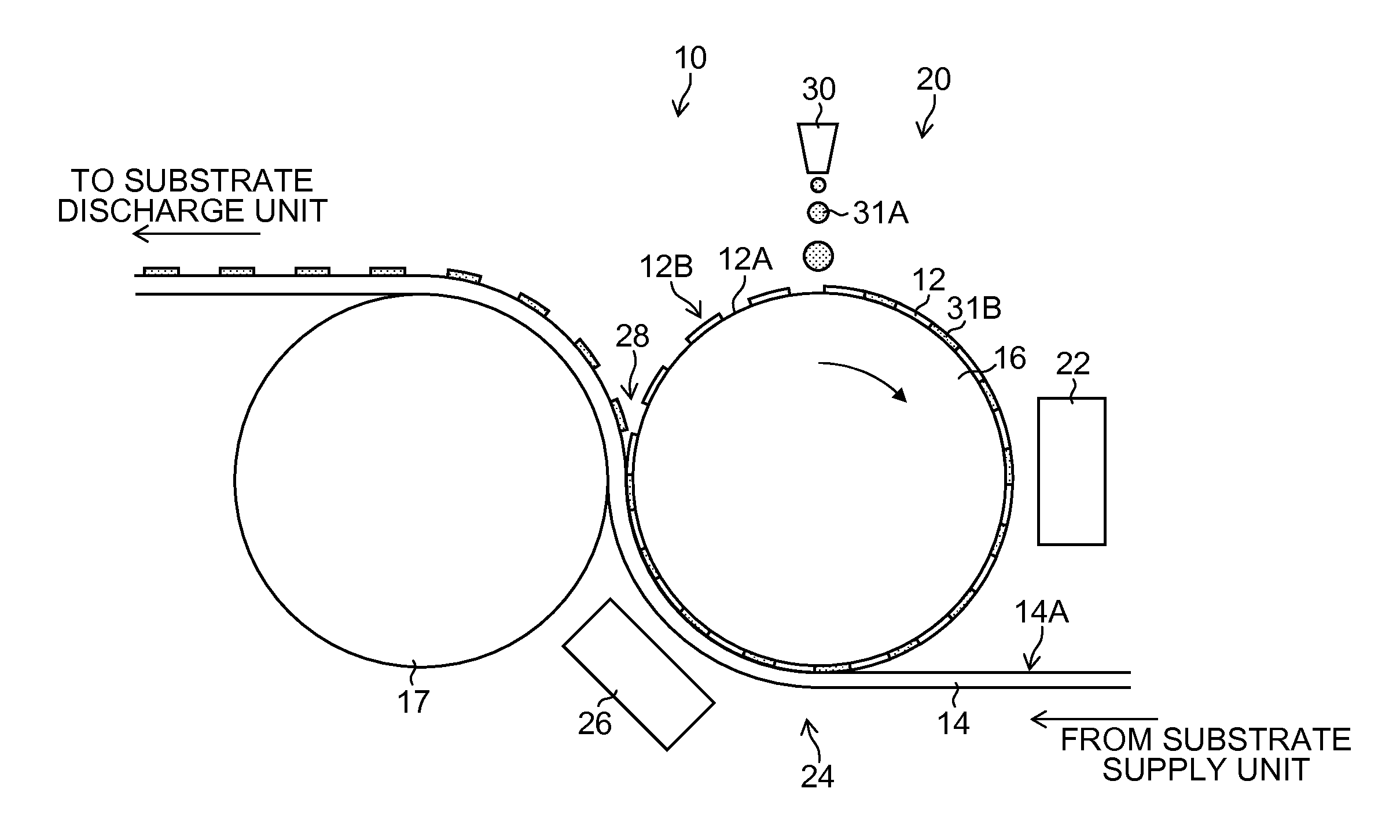
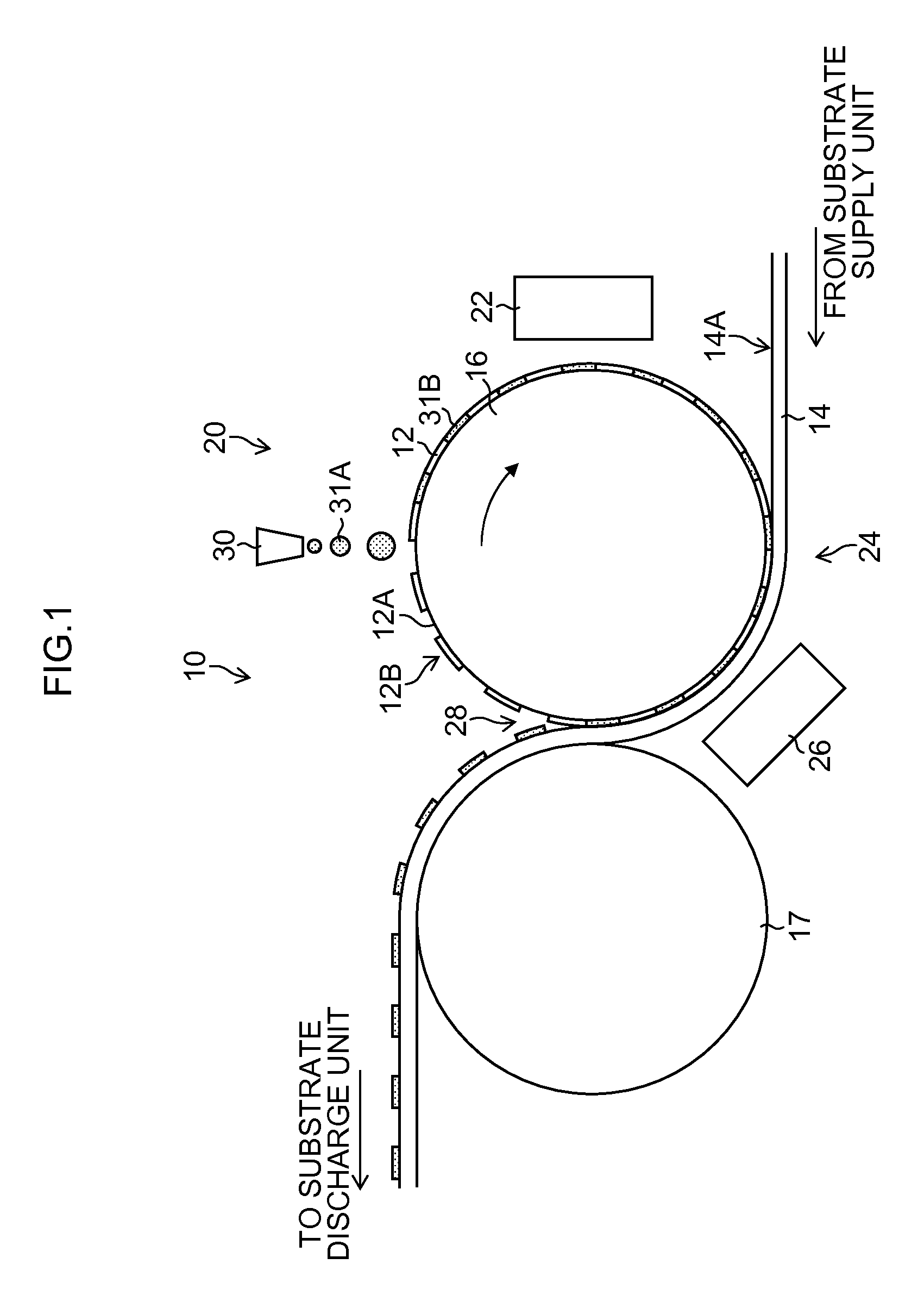
[0039]FIG. 1 is an entire configuration view illustrating a schematic configuration of a printing apparatus according to an embodiment of the present invention. FIG. 1 illustrates a printing apparatus 10 which is applied particularly to printed electronics technology. The printing apparatus 10 uses a printing plate (intaglio plate) 12 having a fine pattern portion (recessed portion) 12A formed therein to transfer (form) a pattern from the printing plate 12 to a substrate (base material) 14 serving as a printing substrate.

[0040]The printing apparatus 10 is configured to include: an inking unit 20 that places ink into (performs an inking process on) the recessed portion 12A of the printing plate 12; a pre-drying unit 22 that performs a drying process on the printing plate 12 following the inking process; a laminating uni...


PUM


Abstract

A printing apparatus includes: a printing plate having a recessed portion formed therein shaped corresponding to a pattern to be formed on a substrate; an inking unit including an inkjet head that performs an inking process of ejecting a liquid into the recessed portion, the liquid having particles as a material of the pattern dispersed therein; a laminating unit that performs a laminating process of laminating the substrate on a surface having the recessed portion formed therein after the inking process; a post-drying unit that performs a drying process on the liquid inside the recessed portion in a state in which the substrate is laminated on the surface having the recessed portion formed therein, thereby to reduce the fluidity of the liquid; and a peeling unit that peels off the substrate from the printing plate after the drying process by the post-drying unit.

Description

CROSS-REFERENCE TO RELATED APPLICATIONS[0001]This application is a Continuation of PCT International Application No. PCT / JP2014 / 056288 filed on Mar. 11, 2014, which claims priority under 35 U.S.C §119(a) to Japanese Patent Application No. 2013-064498 filed on Mar. 26, 2013. Each of the above applications is hereby expressly incorporated by reference, in their entirety, into the present application.BACKGROUND OF THE INVENTION[0002]1. Field of the Invention[0003]The present invention relates to a printing apparatus and a printing method, and more particularly to an inking technique for intaglio plate printing to which an inkjet system is applied.[0004]2. Description of the Related Art[0005]Recent years have seen a use of a technique for forming a micropattern such as metal wiring and electrical wiring patterns for a thin film transistor in a glass substrate, a resin substrate, and other substrates using a printing process. Such a substrate having a micropattern formed by a liquid cont...

Claims


Application Information

Patent Timeline
Patent Type & Authority Patents(United States)
IPC IPC(8): B41J11/00B41F3/36B41M1/10B41J2/005H05K3/12B41F9/06B41F23/04B41J2/01
CPCB41J11/002B41F3/36B41F9/06B41F23/04B41J2/0057B41J2/01B41M1/10H05K3/1275B41F23/0463B41F9/002B41F9/003B41F9/061B41F23/0423H01L27/1292B41J11/00214B41J11/0022
Inventor KODAMA, KENICHI
Owner FUJIFILM CORP
Learn More