Ultrasonic detection method and ultrasonic analysis method

a technology of ultrasonic detection and analysis method, applied in the direction of analysing solids using sonic/ultrasonic/infrasonic waves, measuring devices, instruments, etc., can solve the problems of extended repair cycles, limited non-destructive techniques, and difficult inspection of large and complex objects

Active Publication Date: 2016-11-01
GE INFRASTRUCTURE TECH INT LLC
View PDF52 Cites 2 Cited by
  • Summary
  • Abstract
  • Description
  • Claims
  • Application Information

AI Technical Summary

Problems solved by technology

The inspection of large and complex objects (such as, solid steam turbine rotors) can be very difficult.
In large objects, non-destructive techniques are limited based upon the size of the objects, based upon the complexity of the objects, and / or based upon the materials of the objects.
A failure to identify such features can result in extended repair cycles, limiting availability of operation, and / or system failure.
For example, one known technique, pulse echo, is limited to covering a small volume of a cylindrical solid rotor material in a single pass.
To achieve such inspection in a non-destructive manner, ultrasonic systems can be integrated into the object at a substantial expense, can require complex and / or repeated analysis, can require advanced motion control and / or complex probe positioning control, and combinations thereof, resulting in high costs.

Method used


Image

  • Ultrasonic detection method and ultrasonic analysis method
  • Ultrasonic detection method and ultrasonic analysis method

Examples


Embodiment Construction

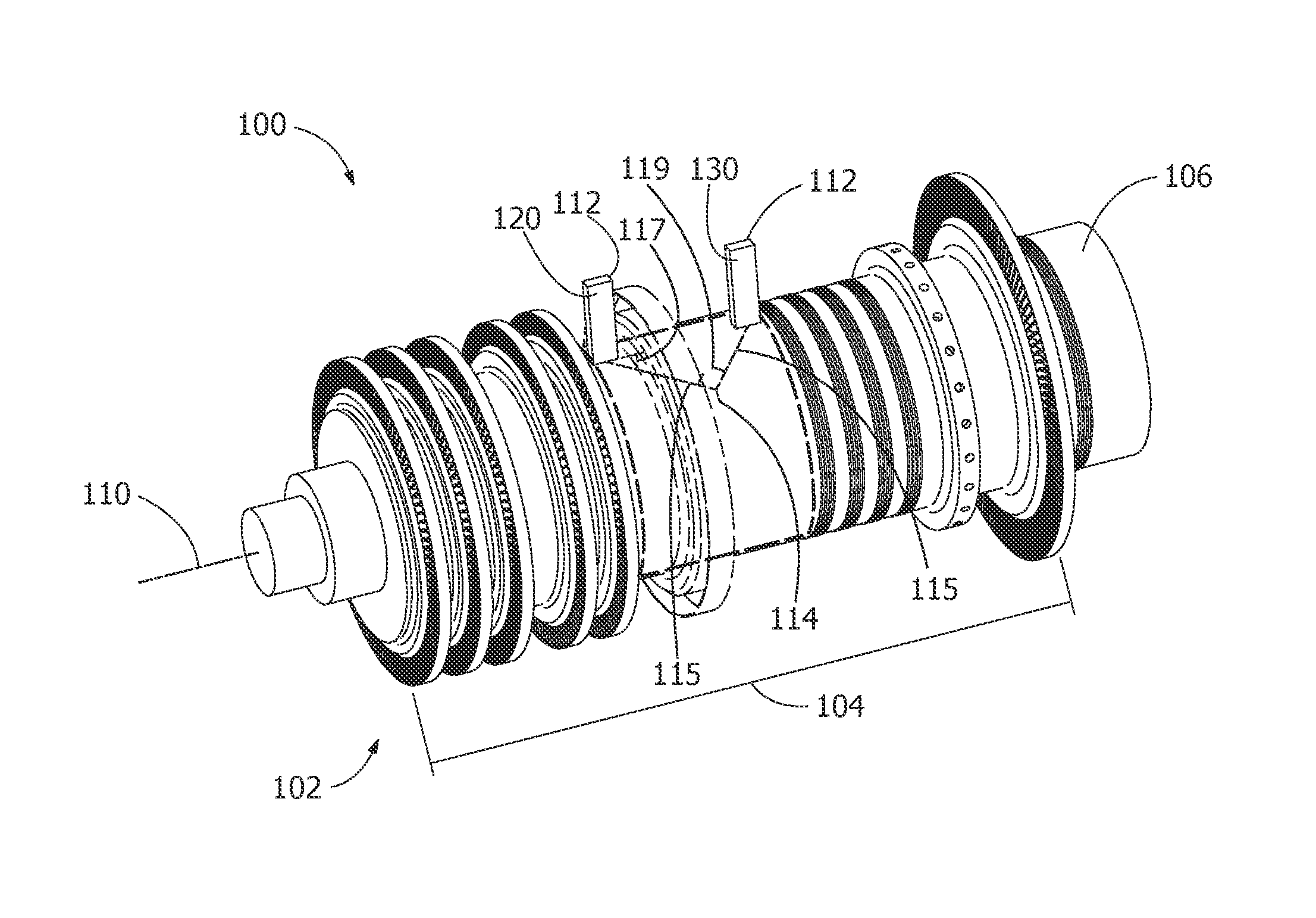
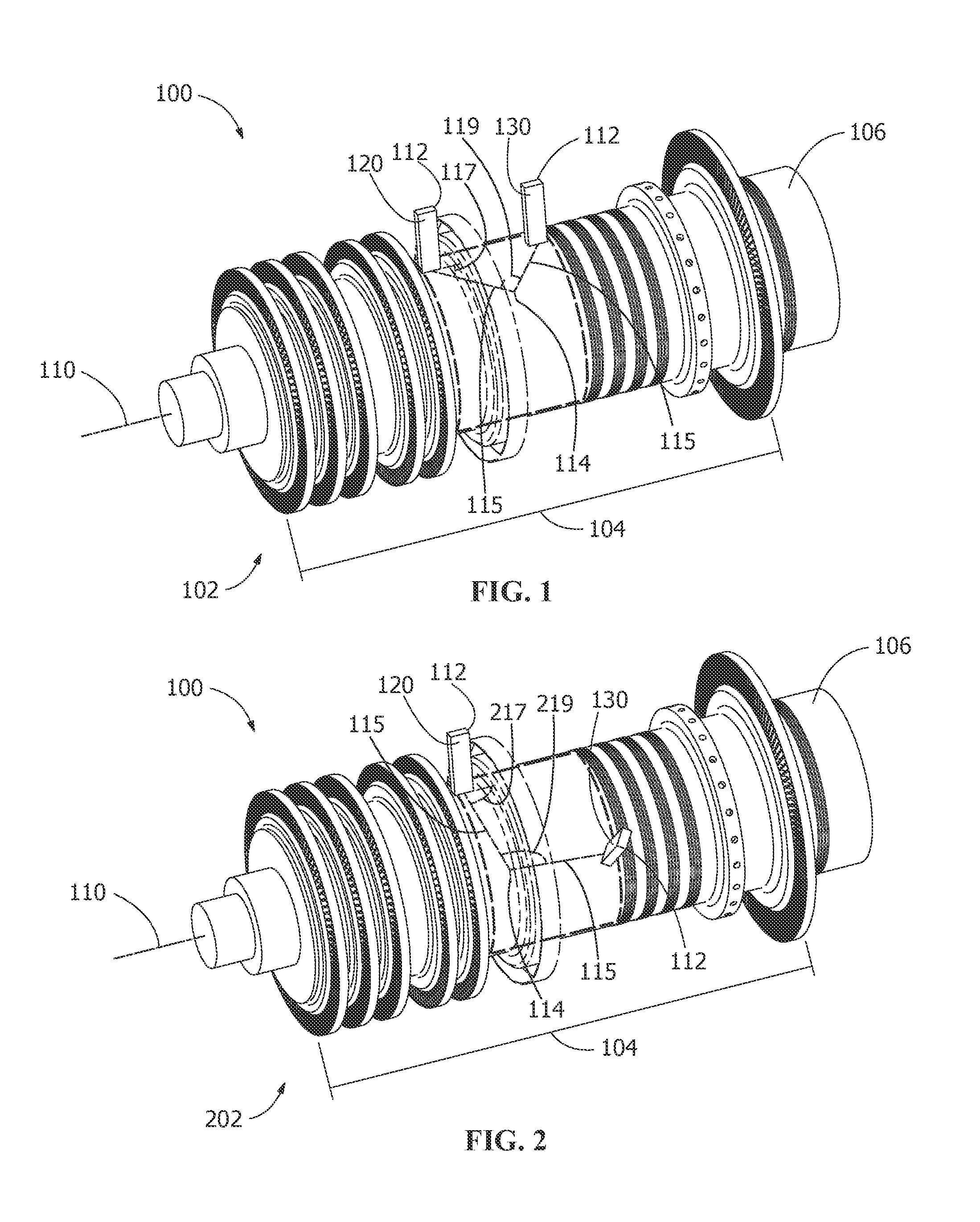
[0013]Provided is an exemplary ultrasonic detection method. Embodiments of the present disclosure, in comparison to methods not utilizing one or more features disclosed herein, permit non-destructive analysis of features in large solid or substantially solid objects, reduce or eliminate repair and / or inspection cycles, utilize two or more probes in a pitch-catch manner, avoid integration of probes into large bodies, or a combination thereof.

[0014]FIGS. 1 and 2 show embodiments of an ultrasonic detection system 100 for performing an ultrasonic detection method. The system 100 includes two or more ultrasonic phased array devices 112 arranged with respect to a revolutionary body 106 to be measured. The revolutionary body 106 is rotatable about a centerline, and is any suitable object including, but not limited to, objects manufactured from a monolithic forging, such as, a turbine rotor, a shaft of a solid steam rotor, a portion underneath a turbine rotor wheel, or a blade attachment.

[0...


PUM

PropertyMeasurementUnit
operational frequencyaaaaaaaaaa
ultrasonic detectionaaaaaaaaaa

Abstract

Ultrasonic detection methods are disclosed. The method includes providing an ultrasonic detection system having a transmitting phased array device and a receiving phased array device. A phased array wave is transmitted through a revolutionary body from the transmitting phased array device to the receiving phased array device, thereby obtaining ultrasonic detection information about the revolutionary body. In another embodiment, the method includes positioning the transmitting phased array device and the receiving phased array device on a periphery of a turbine rotor, transmitting a phased array wave into the turbine rotor, the phased array wave not reflecting off of a reflecting feature, adjusting the positioning of the transmitting phased array devices on the periphery of the turbine rotor, and transmitting the phased array wave into the turbine rotor, the phased array wave reflecting off of a reflecting feature. The reflected phased array wave is received by the receiving phased array device.

Description

FIELD OF THE INVENTION[0001]The present invention is directed to non-destructive testing methods. More specifically, the present invention is directed to ultrasonic detection and analysis methods.BACKGROUND OF THE INVENTION[0002]The inspection of large and complex objects (such as, solid steam turbine rotors) can be very difficult. Such inspection is important for identifying features, such as, asperities, voids, defects, fatigued material, cracks, and / or material variations. In large objects, non-destructive techniques are limited based upon the size of the objects, based upon the complexity of the objects, and / or based upon the materials of the objects. A failure to identify such features can result in extended repair cycles, limiting availability of operation, and / or system failure.[0003]Some commercial inspection systems are available to provide the inspection of large objects. Known ultrasonic techniques use single probe approaches, limiting the volume of material that can be i...

Claims


Application Information

Patent Timeline
Patent Type & Authority Patents(United States)
IPC IPC(8): G01N29/11G01N29/26
CPCG01N29/262G01N29/11G01N2291/2693G01N29/043G01N29/069
Inventor FREDA, MICHAEL CHARLESREED, FRANCIS ALEXANDER
Owner GE INFRASTRUCTURE TECH INT LLC
Why Eureka
Try Eureka